
Method for detecting state of secondary battery and device for detecting state of second battery

Inactive Publication Date: 2006-03-30
PANASONIC EV ENERGY CO LTD
View PDF12 Cites 36 Cited by
  • Summary
  • Abstract
  • Description
  • Claims
  • Application Information

AI Technical Summary

Benefits of technology

[0008] The present invention is achieved in view of the foregoing problems, and it is an object of the present invention to provide a method for detecting the state of a secondary battery and a device for detecting the state of a secondary battery that can improve the accuracy in estimating the value of internal resistance of the secondary battery as vehicles are running, and that can diagnose the deterioration level and an anomaly of the secondary battery.
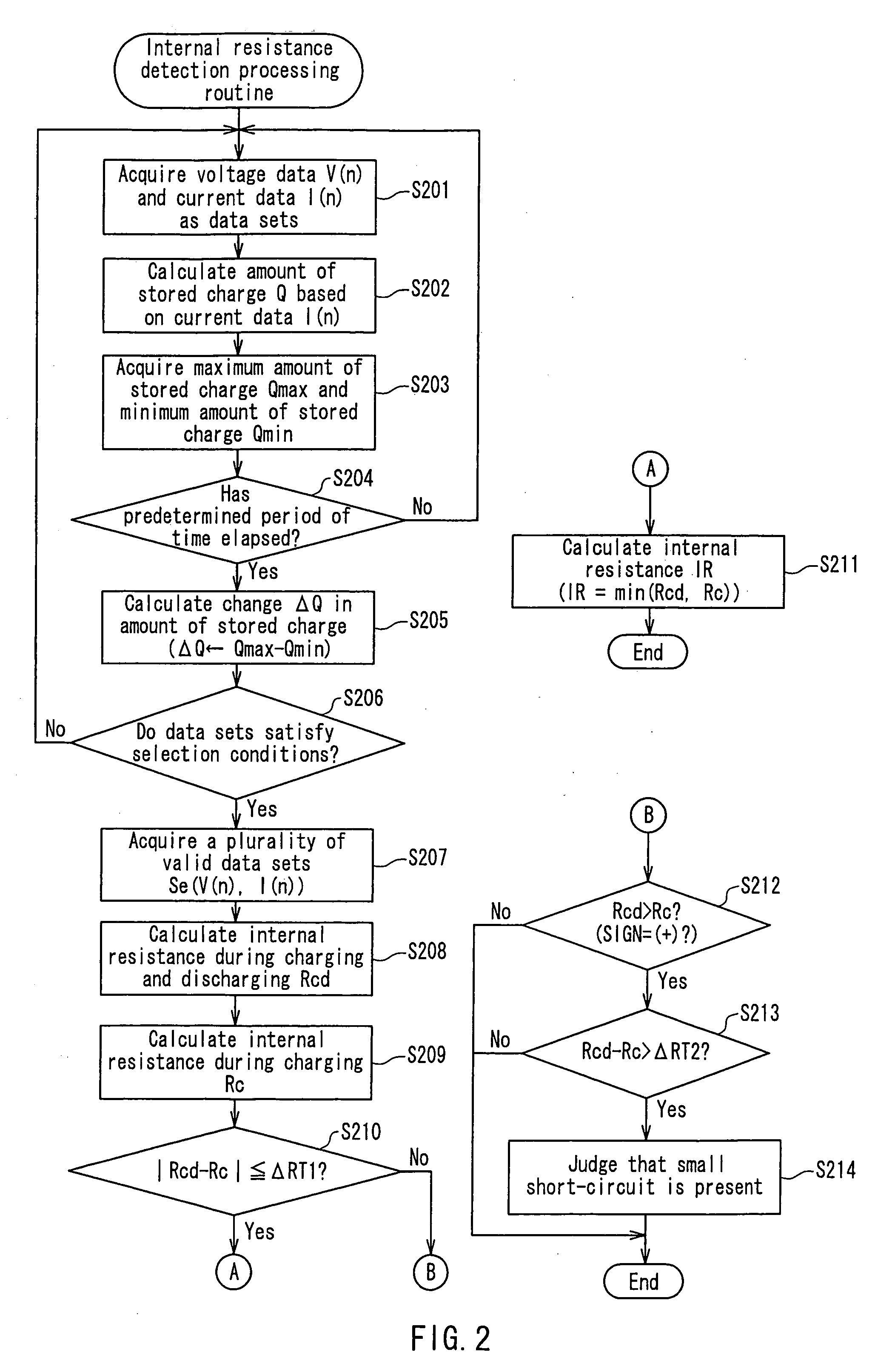
[0010] When the secondary battery suffers deterioration (small short-circuit), the voltage during charging is almost equal to the ordinary voltage, so that the value of internal resistance obtained from the voltage-current linear approximation during charging is the original value of internal resistance. On the other hand, in this case, the voltage during discharging decreases, so that the value of internal resistance obtained from the voltage-current linear approximation during charging and discharging and the value of internal resistance obtained from the voltage-current linear approximation during charging are not equal to each other. For this reason, the method for detecting the state of a secondary battery according to the present invention calculates the value of internal resistance more accurately by referencing the value of internal resistance obtained from the voltage-current linear approximation during charging in addition to the value of internal resistance obtained from the voltage-current linear approximation during charging and discharging.
[0014] Moreover, it is preferable that the method for detecting the state of a secondary battery according to the present invention further includes a step of setting the first predetermined value and a second predetermined value according to the temperature of the secondary battery. In this manner, it is possible to obtain a correct value of internal resistance giving consideration to a change in the battery temperature, and it also is possible to make a correct judgment on deterioration.
[0017] When the secondary battery suffers deterioration (small short-circuit), the voltage during charging is almost equal to the ordinary voltage, so that the value of internal resistance obtained from the voltage-current linear approximation during charging is the original value of internal resistance. On the other hand, in this case, the voltage during discharging decreases, so that the value of internal resistance obtained from the voltage-current linear approximation during charging and discharging and the value of internal resistance obtained from the voltage-current linear approximation during charging are not equal to each other. For this reason, the device for detecting the state of a secondary battery according to the present invention calculates the value of internal resistance more accurately by referencing the value of internal resistance obtained from the voltage-current linear approximation during charging in addition to the value of internal resistance obtained from the voltage-current linear approximation during charging and discharging.

Problems solved by technology

Moreover, in some cases, a small short-circuit occurs in the secondary battery, resulting in a deterioration in the secondary battery, and thus the voltage V decreases only during discharging.
Consequently, it is difficult to obtain a correct value of internal resistance with the method described above.

Method used


Image

  • Method for detecting state of secondary battery and device for detecting state of second battery
  • Method for detecting state of secondary battery and device for detecting state of second battery
  • Method for detecting state of secondary battery and device for detecting state of second battery

Examples


Embodiment Construction

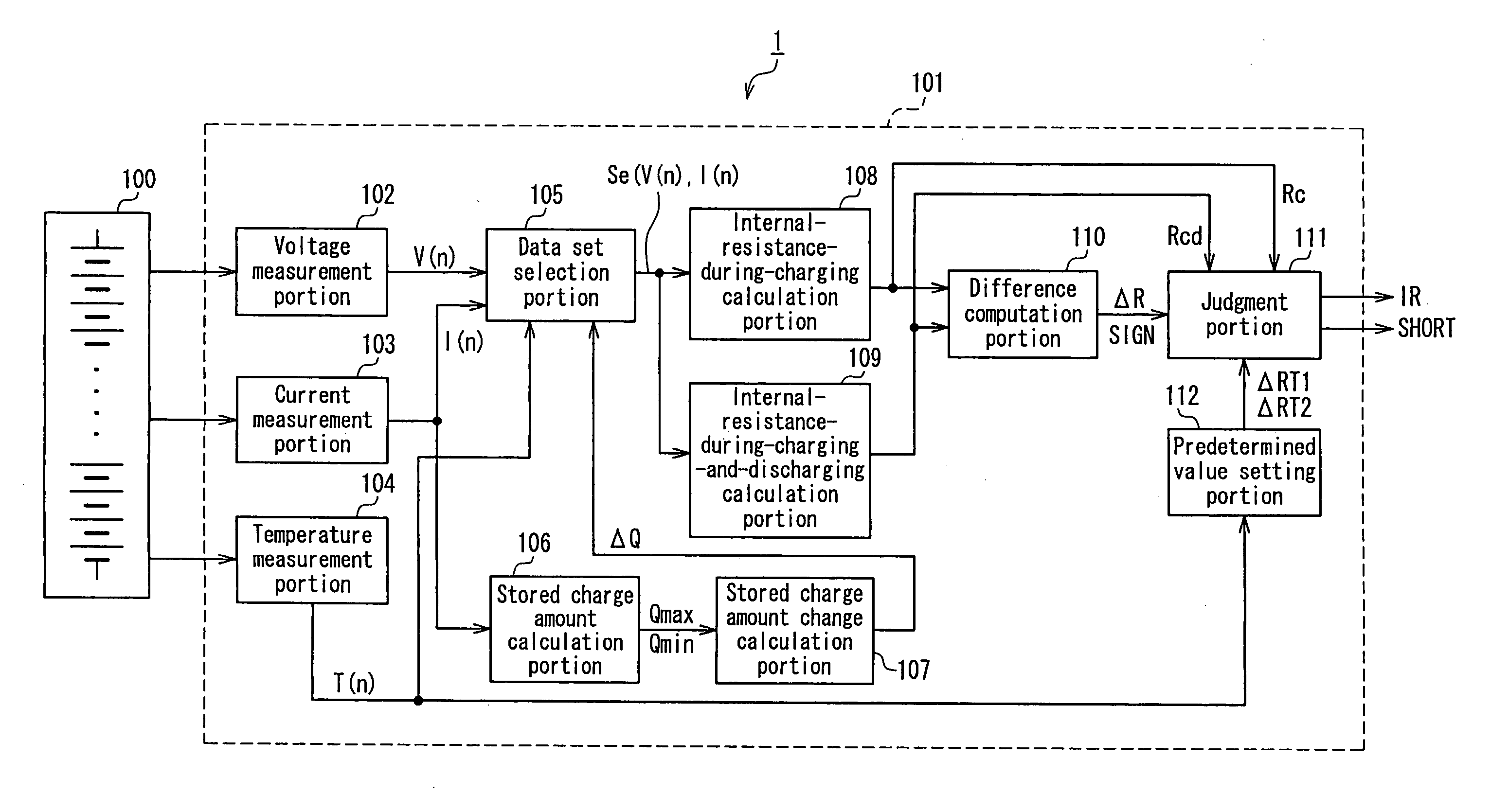
[0023] Hereinafter, preferred embodiments of the present invention will be described with reference to the drawings. FIG. 1 is a block diagram showing an example of the configuration of a battery pack system according to an embodiment of the present invention.

[0024] As shown in FIG. 1, the battery pack system 1 is provided with a secondary battery 100 that is formed by combining a plurality of single cells or unit cells and a battery electronic control unit (hereinafter, abbreviated as “battery ECU”) 101 that contains the device for detecting the state of a secondary battery according to the present invention as a part of a microcomputer system.

[0025] In the battery ECU 101, reference numeral 102 indicates a voltage measurement portion that measures the terminal voltage of the secondary battery 100 detected by a voltage sensor (not shown) at a predetermined sampling period (one second, for example) to obtain voltage data V(n). Reference numeral 103 indicates a current measurement ...


PUM


Abstract

Based on a plurality of valid data sets from a data set selection portion, an internal-resistance-during-charging calculation portion calculates the value Rc of internal resistance during charging from the slope of a voltage-current linear approximation during charging, and an internal-resistance-during-charging-and-discharging calculation portion calculates the value Rcd of internal resistance during charging and discharging from the slope of a voltage-current linear approximation during charging and discharging. A judgment portion compares the absolute value ΔR of the difference between Rcd and Rc that has been calculated by a difference computation portion with a first predetermined value ΔRT1, and when ΔR≦ΔRT1 is satisfied, the judgment portion outputs Rcd or Rc, whichever is smaller, as the value of internal resistance of a secondary battery.

Description

BACKGROUND OF THE INVENTION [0001] 1. Field of the Invention [0002] The present invention relates to a technology for estimating, while driving, the internal resistance (IR) of a secondary battery such as a nickel-metal hydride (Ni-MH) battery installed in a pure electric vehicle (PEV), a hybrid electric vehicle (HEV), or the like as a source of motive power for the motor and a source of driving power for various loads and for detecting the state of deterioration and an anomaly of the secondary battery. [0003] 2. Description of Related Art [0004] Conventionally, it is well known that the internal resistance of a secondary battery is calculated to detect the state of deterioration or an anomaly of the secondary battery. In HEVs and other electric vehicles, when an output from the engine is greater than the motive power that is necessary for the vehicles to run, the surplus motive power is used to drive the generator so as to charge the secondary battery. Conversely, in HEVs and other...

Claims


Application Information

Patent Timeline
IPC IPC(8): H02J7/00
CPCG01R31/3648H02J7/0047G01R31/3662G01R31/389
Inventor MINAMIURA, KEIICHI
Owner PANASONIC EV ENERGY CO LTD
Learn More