
Electrode and battery

a battery and electrode technology, applied in the field of batteries, can solve the problems of increasing manufacturing costs, inability to form a sufficient coat, and difficulty in maintaining about 60% of the discharge capacity, and achieve the effect of improving battery characteristics and effective coa

Inactive Publication Date: 2006-03-23
SONY CORP
View PDF3 Cites 55 Cited by
  • Summary
  • Abstract
  • Description
  • Claims
  • Application Information

AI Technical Summary

Benefits of technology

[0004] In view of the foregoing problems, it is an object of the invention to provide an electrode and a battery coverable of improving battery characteristics by forming an effective coat.

Problems solved by technology

However, actually, the electrolytic solution is gradually reacted with the electrode active material and decomposed.
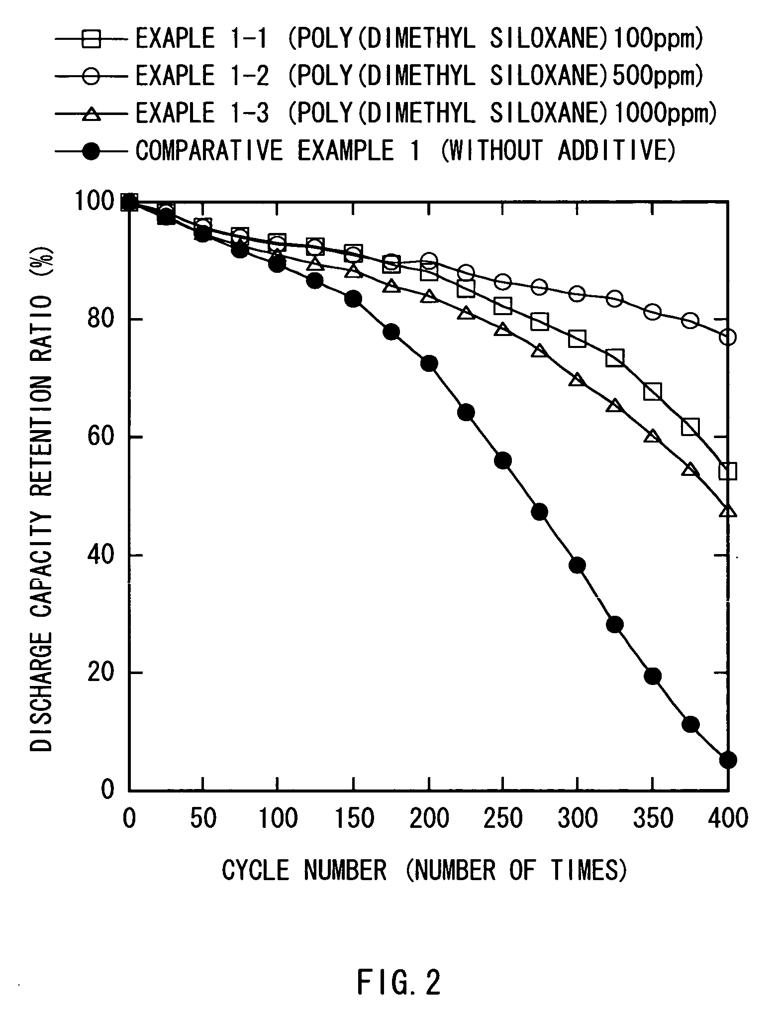
Therefore, the discharge capacity becomes about 60% at about the 300th cycle, and it has been difficult to realize maintaining about 60% of a discharge capacity after repetition of about 500 cycles of charge and discharge.
However, when a traditional additive is used, it is not possible to form a sufficient coat unless a certain amount of the additive is added.
Therefore, even though targeted characteristics can be improved, there have been problems such as that other characteristics are lowered, and that the manufacturing cost is increased.

Method used


Image

  • Electrode and battery
  • Electrode and battery
  • Electrode and battery

Examples


examples 1-1 to 1-3

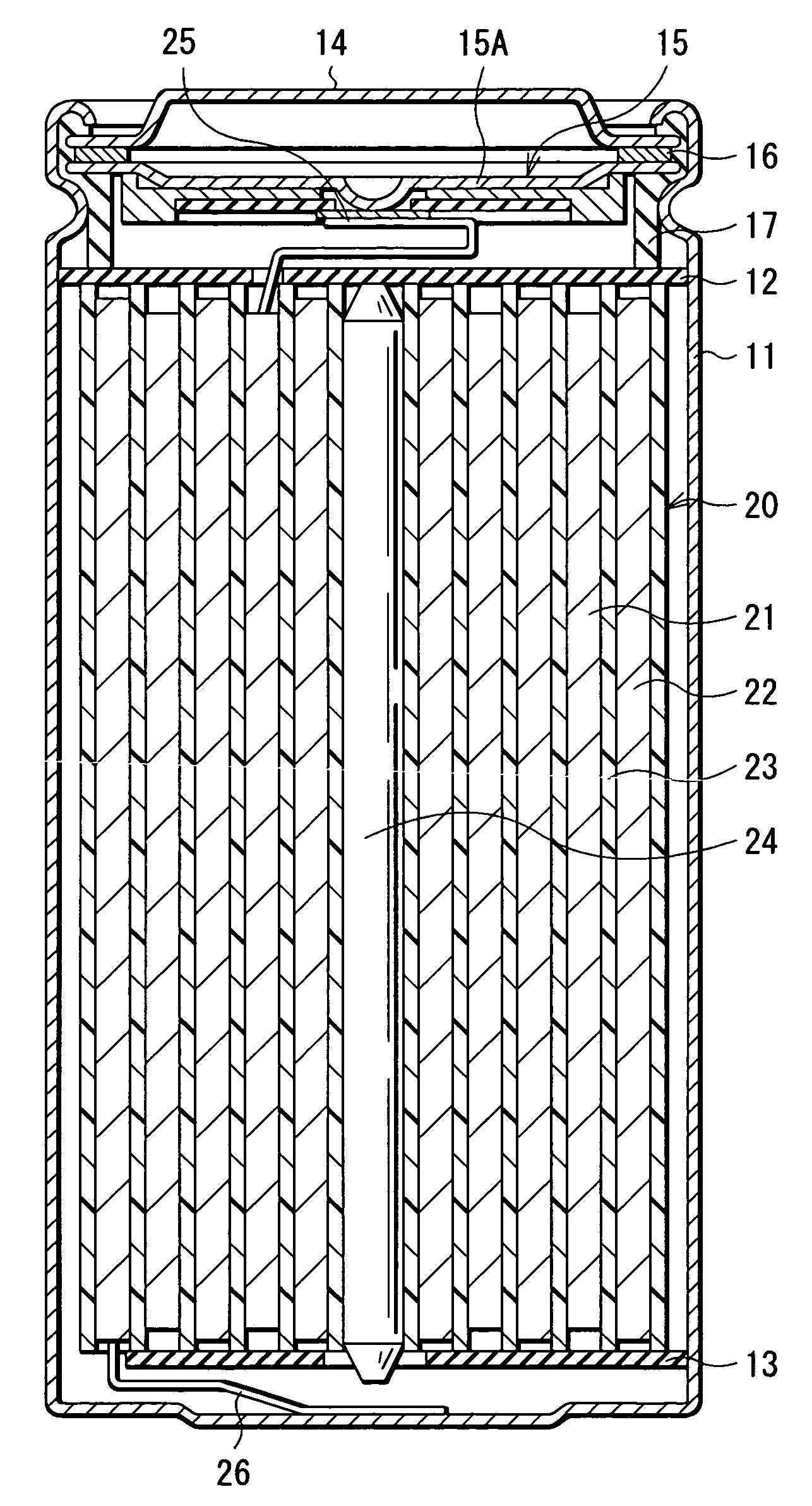
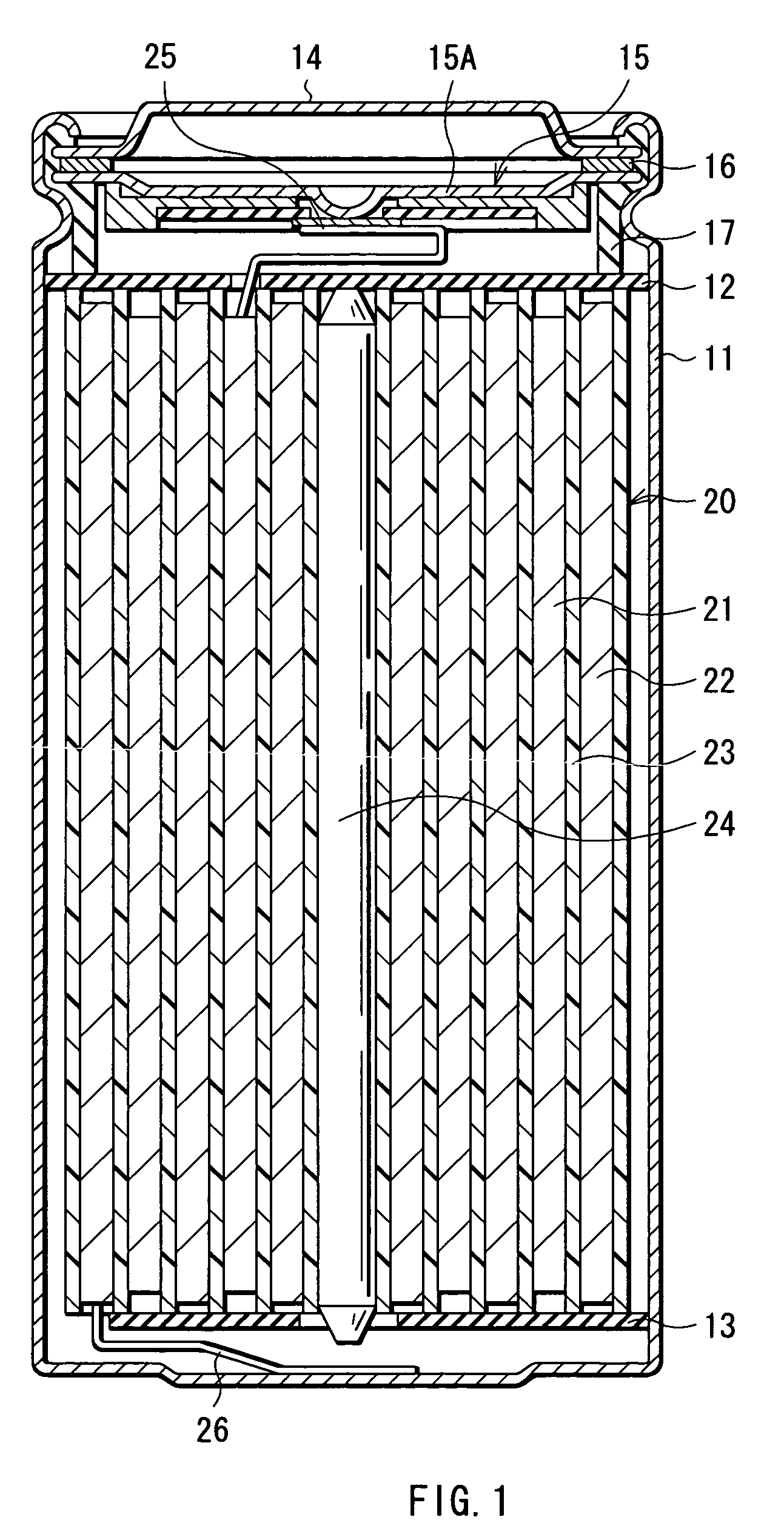
[0049] First, 64 parts by mass of lithium cobaltate (LiCoO2) as the cathode active material, 3 parts by mass of graphite as the conductive agent, and 3 parts by mass of polyvinylidene fluoride as the binder were uniformly mixed. After that, N-methylpyrrolidone was added to the mixture to obtain a cathode mixture coating liquid. Next, a cathode current collector made of an aluminum foil having a width of 56 mm, a length of 550 mm, and a thickness of 20 μm was uniformly coated with the obtained cathode mixture coating liquid, which was dried to form a cathode mixture layer having a thickness of 70 μm on the both faces of the cathode current collector. Thereby, the cathode 21 was fabricated. After that, the cathode lead 25 made of aluminum was mounted to an end of the cathode current collector.

[0050] Further, 94 parts by mass of graphite as the anode active material and 6 parts by mass of polyvinylidene fluoride as the binder were uniformly mixed. N-methylpyrrolidone was added to the ...

examples 2-1 to 2-4

[0057] As Examples 2-1,2-2, 2-3, and 2-4, secondary batteries were fabricated as in Example 1-2, except that instead of poly (dimethyl siloxane), poly (methyl hydro siloxane), poly (methyl phenyl siloxane), poly (hexafluoro propylene oxide), and perfluoro pentadecane, which are insoluble into the electrolytic solution and have a kinetic viscosity of 100 mm2 / S and a surface tension of about 20 mN / m were respectively used. The secondary batteries of Examples 2-1 to 2-4 were also disassembled and observed as in Example 1-2. In the result, it was confirmed that a coat containing poly (methyl hydro siloxane), poly (methyl phenyl siloxane), poly (hexafluoro propylene oxide), or perfluoro pentadecane was formed on the surface of the cathode 21 and the anode 22. Further, as in Example 1-2, a charge and discharge test was performed to examine cycle characteristics. The results thereof are shown in FIG. 3 along with the results of Example 1-2 and Comparative example 1.

[0058] As evidenced by ...


PUM


Abstract

An electrode and a battery coverable of improving cycle characteristics by forming an effective coat are provided. A cathode (21) and an anode (22) are wound with a separator (23) impregnated with an electrolytic solution inbetween. On the surface of the cathode (21) or the anode (22), a coat containing a compound, which has a smaller surface tension than of the electrolytic solution and is insoluble into the electrolytic solution, specifically, a coat containing siloxane such as poly (dimethyl siloxane), poly (methyl hydro siloxane), and poly (methyl phenyl siloxane), or perfluoro polyether such as poly (hexafluoro propylene oxide), or perfluoro alkane such as perfluoro pentadecane is provided. Thereby, without using a great deal of the compound for forming the coat, the coat effective to inhibit decomposition reaction of the electrolytic solution is formed.

Description

TECHNICAL FIELD [0001] The present invention relates to a battery including a cathode, an anode, and an electrolytic solution, particularly using lithium (Li) and the like as electrode reacting species, and an electrode used for it. BACKGROUND ART [0002] In recent years, many portable electronic devices such as a combination camera (video tape recorder), a digital still camera, a mobile phone, a personal digital assistance, and a laptop computer have been introduced, and downsizing and weight saving of these portable electronic devices have been made. Along with these situations, researches and developments to improve an energy density of a battery, particularly a secondary battery as a portable power source for these electronic devices have been actively promoted. Specially, a lithium ion secondary battery, using a carbon material as an anode active material and using a mixture of ester carbonate for an electrolyte is widely in practical use, since such a lithium ion secondary batt...

Claims


Application Information

Patent Timeline
IPC IPC(8): H01M2/16H01M10/40H01M4/13H01M4/62H01M10/05H01M10/052H01M10/0564H01M10/0567H01M10/0569H01M10/0587
CPCH01M4/13Y02E60/122H01M10/052H01M4/62Y02E60/10Y02P70/50H01M10/05
Inventor KAWASHIMA, ATSUMICHIENDO, TAKUYA
Owner SONY CORP
Learn More