
Blood component separation system with stationary separation chamber

a separation system and blood component technology, applied in the direction of reciprocating system, centrifuge, instruments, etc., can solve the problems of inability to meet the needs of large-scale blood separation operations, add costs and complexity to disposable blood pathway sets, and components that do not use centrifuge technology, etc., to achieve the effect of reducing complexity, cost and risk of loss of sterility

Inactive Publication Date: 2006-03-16
RAGUSA MICHAEL +2
View PDF32 Cites 44 Cited by
  • Summary
  • Abstract
  • Description
  • Claims
  • Application Information

AI Technical Summary

Benefits of technology

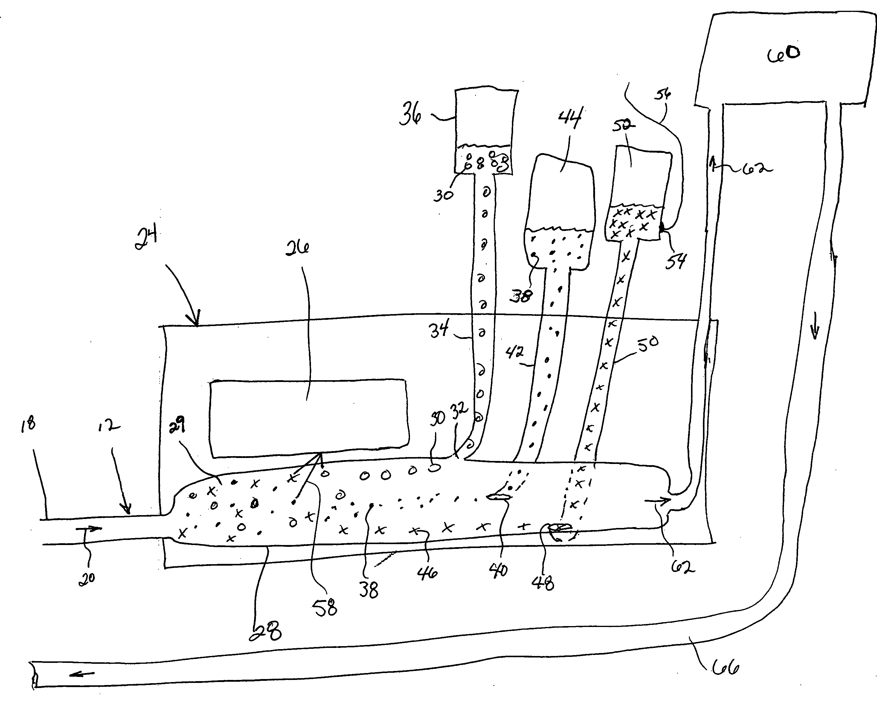
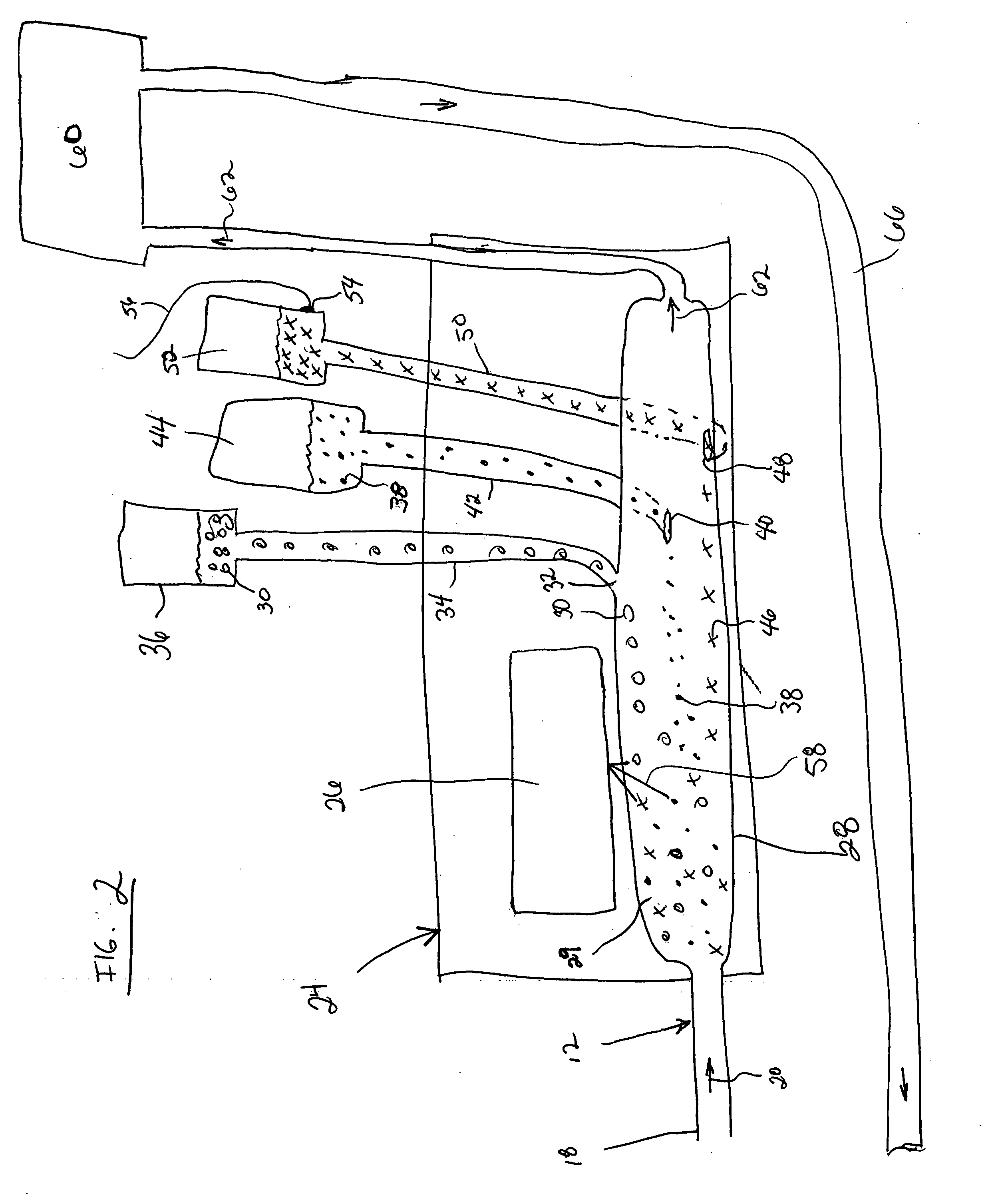
[0013] In addition to the basic system outlined above, additional elements may be added to the system to optimize system performance for a given procedure. Anticoagulants may be introduced at the inlet of the system to, not only prevent coagulation of the blood in the pathway, but also to optimize the viscosity of the blood for the separation process. The anticoagulant may be introduced from a reservoir bag through a conduit such as tubing and its rate of flow controlled by an anticoagulant pump. Alternatively, other materials suitable for diluting blood may be used in place of anticoagulant, such as plasma or saline. In the case of a blood product such as plasma, it is preferable to use the patient's or donor's own plasma. Therefore, in such a system, plasma is one of the components separated by the system and the plasma reservoir is configured to have an outlet joined to a conduit that is selectively opened to the blood pathway to introduce the plasma.
[0022] It is another aspect of the invention to provide a high-speed blood component separation system that uses a stationary separation chamber to reduce complexity, cost and risk of loss of sterility in the blood pathway.

Problems solved by technology

The design of high-speed blood processing equipment such as the systems mentioned above is limited by several factors.
However, reliably and economically maintaining a sterile fluid pathway with the moving centrifuge bowl has remained a challenge.
However, both approaches add costs and complexity to disposable blood pathway sets which demand low cost pricing and extended reliability to remain commercially viable.
Alternative methods of separating blood into its constituent components that do not use centrifuge technology are available but have not been viable alternatives for a large scale blood separation operations.
However, such processes are slow and require periods of stagnation of the blood, which increrases problems with coagulation.

Method used


Image

  • Blood component separation system with stationary separation chamber
  • Blood component separation system with stationary separation chamber
  • Blood component separation system with stationary separation chamber

Examples


Embodiment Construction

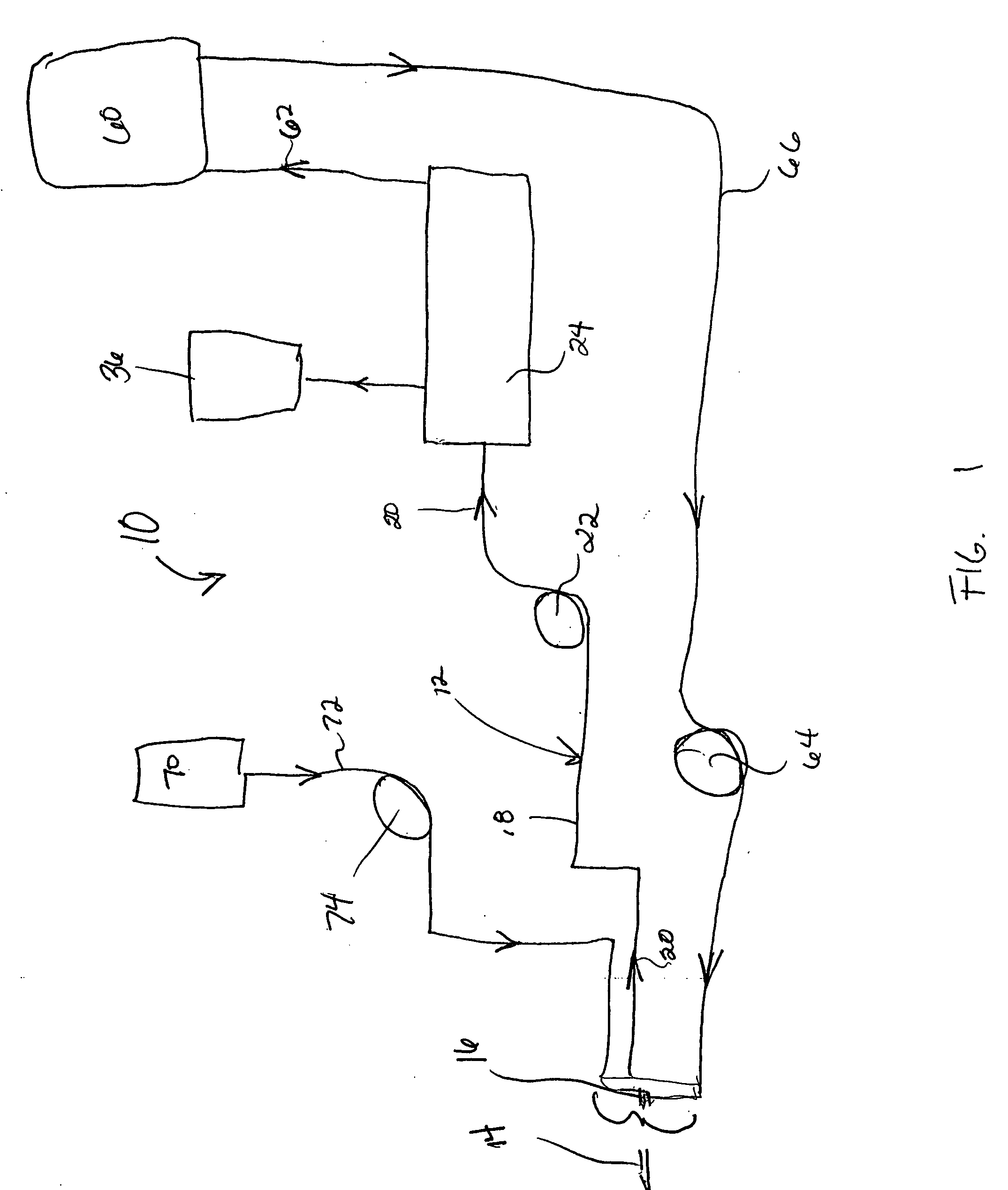
[0033]FIG. 1 shows a diagrammatic illustration of the components and configuration of a blood component separation system 10 using optical trapping technology. The system is configured to separate one or more constituent components from blood as it passes through the system. For example, the components separated may include red blood cells, plasma or platelet rich plasma. Additionally, optical traps may be configured to separate proteins, prions, viruses, bacteria and other contaminants and particles from the blood flowing through the system. In addition the optical trap may be configured to detect the presence of unique cells such as disease cells (e.g., sickle cells) or infected cells, the presence of which would cause a donated blood sample to be rejected. All the various components, cells, portions of cells, bacteria and contaminants are referred to generally in this application as “components”. It should be understood that reference to “components” can signify any one of the af...


PUM


Abstract

Provided is a blood processing system having a stationary component separation chamber. Individual blood components as well as other particles and contaminates are separated from blood flowing through the separation chamber by optical traps configured to manipulate specific components are projected into the flow field of the chamber. Cells or particles of the selected components that are manipulated by the optical traps then may be directed from the flow field to individual reservoirs to collect quantities of the selected components.

Description

FIELD OF THE INVENTION [0001] The present invention relates to blood processing equipment. In particular, the invention pertains to systems and methods for the separation of one or more constituent components from blood using optical trapping projected through a stationary separation chamber. BACKGROUND OF THE INVENTION [0002] Systems and processes for separating blood into its constituent components are well known. Commercial systems for rapidly processing large volumes of blood in a continuous flow process are available from Haemonetics Corporation of Braintree, Mass. In particular, equipment such as the MCS® line of equipment and Cell Saver ® 5 system available from Haemonetics are configured to receive blood directly from a patient or donor, transfer the blood to a blood processing chamber, separate components from the blood and direct those separated components to individual component reservoirs for later use or return to the patient while returning the remaining blood flow wit...

Claims


Application Information

Patent Timeline
Patent Type & Authority Applications(United States)
IPC IPC(8): B04B11/02
CPCA61M1/3693G02B27/4205G02B27/42G02B21/32A61M1/30A61M1/302A61M1/303A61M1/308A61M1/3696A61M1/3616
Inventor RAGUSA, MICHAELSTACEY, GARY R.PAGES, ETIENNE
Owner RAGUSA MICHAEL
Learn More