
Rotating stuffing box with split standpipe

a technology of standpipe and stuffing box, which is applied in the direction of drilling pipes, drilling casings, borehole/well accessories, etc., can solve the problems of difficult servicing or replacing the stuffing box, the harsh operating environment of the pcp implementation, and the sealing of the pressurized production fluid

Inactive Publication Date: 2006-03-09
WEATHERFORD TECH HLDG LLC
View PDF7 Cites 23 Cited by
  • Summary
  • Abstract
  • Description
  • Claims
  • Application Information

AI Technical Summary

Benefits of technology

[0011] In another respect, the present invention provides a method of replacing a stuffing box. The method includes providing a wellhead and a drive system, wherein the drive system comprises a top mounted rotating stuffing and a drive unit. The method also includes providing a safety clamp for securing the weight of the drive string. The method also includes shutting down the well, securing the weight of the drive string by placing the safety clamp on an exposed portion of the drive string at the surface and holding the drive unit stationary. The method also includes rotating the stuffing box a quarter turn in either direction, relative to the drive unit and lifting the stuffing box upwards and removing the stuffing box from the drive system.

Problems solved by technology

A major problem associated with downhole PCP implementations is sealing the pressurized production fluid and preventing it from escaping into the atmosphere from surface equipment.
The harsh operating environment of a PCP implementation necessitates regular servicing of stuffing boxes due to failed bearings and seals within.
Servicing or replacing stuffing boxes prove to be difficult in the case of bottom mount stuffing boxes because they are difficult to gain access to.
Those skilled in the art will understand that under rigorous conditions, rope type packings have a tendency to lose shape, or “weep”, which renders these packings ineffective for containing pressurized production fluids.
Further, available top mounted stuffing boxes tend to damage other components of the drive system, such as a drive unit.

Method used


Image

  • Rotating stuffing box with split standpipe
  • Rotating stuffing box with split standpipe
  • Rotating stuffing box with split standpipe

Examples


Embodiment Construction

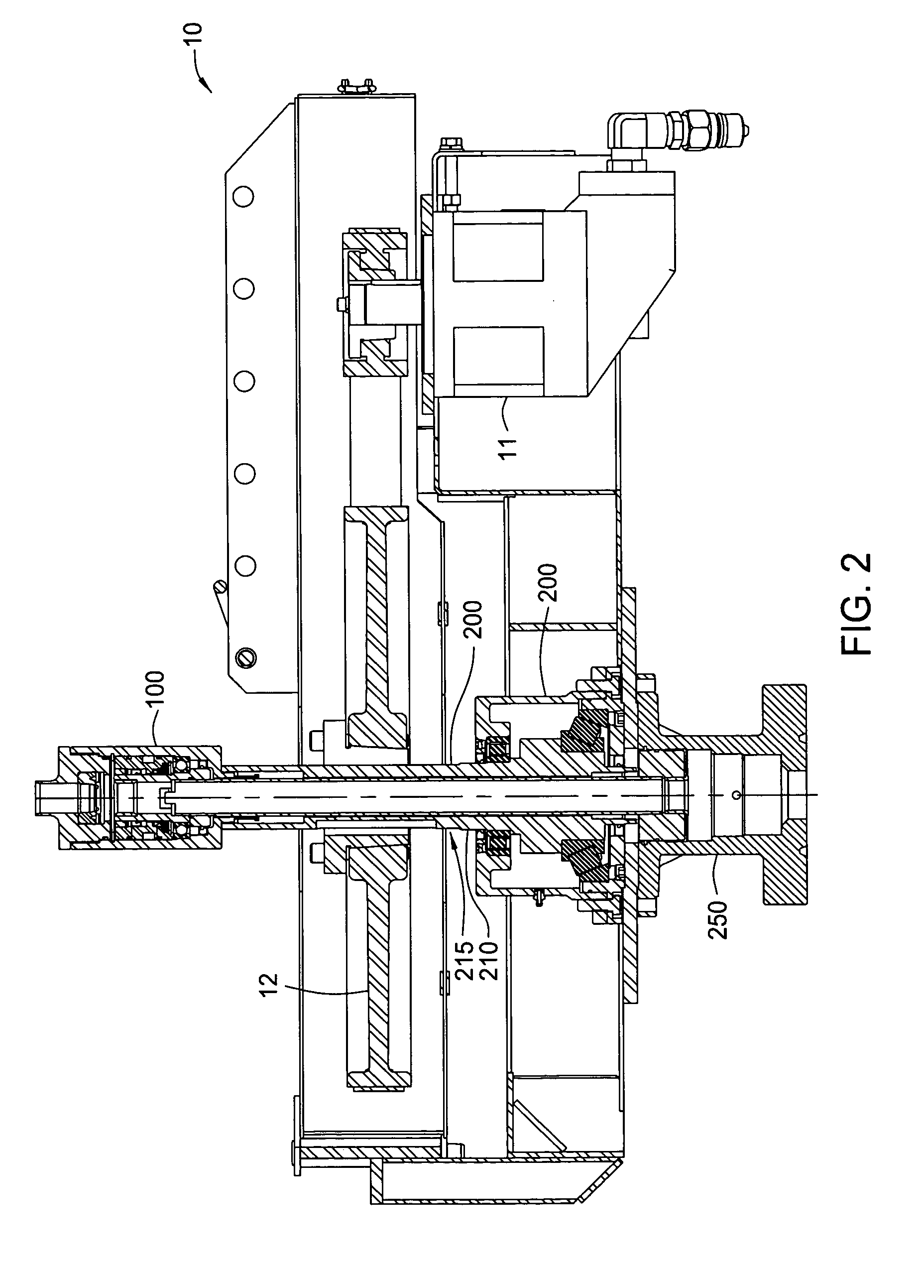
[0020] The apparatus and methods of the present invention, in the context of downhole pump implementations, provide the sealing of production fluid from the environment using a top-mounted rotating stuffing box.

[0021] The discussion below focuses primarily on utilizing top-mounted rotating stuffing boxes together with a split standpipe configuration for use with downhole pump implementations, such as progressing cavity pumps (PCP's). The principles of the present invention also allow for the quick installation or removal of the stuffing box without the need to remove other components such as a corresponding drive unit belonging to a drive system.

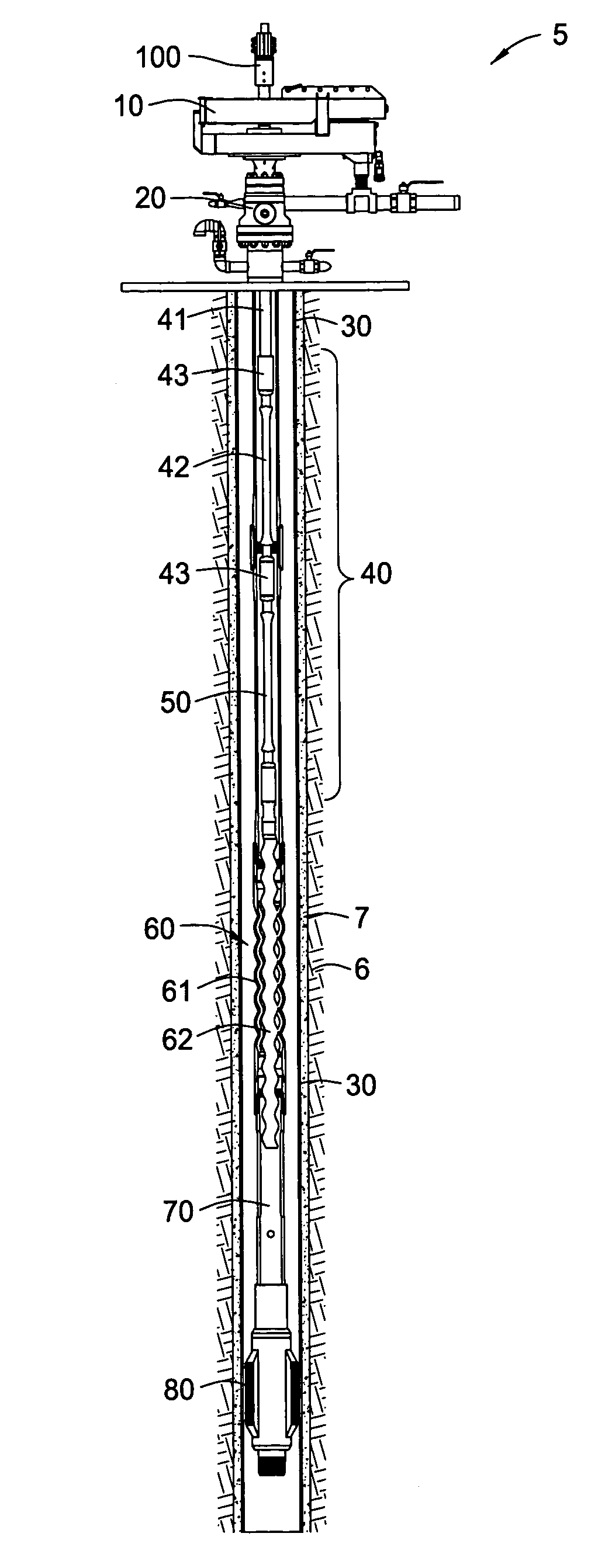
[0022]FIG. 1 presents a cross-sectional view of a wellbore 5. As illustrated, the wellbore 5 has a string of casing 30 fixed in the formation 6 by cured cement 7. The wellbore 5 also includes a downhole PCP implementation in accordance with one embodiment of the present invention. Surface components of the PCP implementation include a hydr...


PUM


Abstract

A system comprising a top mounted rotating stuffing box is provided for use with downhole pump (e.g., Progressing Cavity Pump) applications. The system also includes a split standpipe configuration that allows the stuffing box to be quickly installed or removed as needed. The split standpipe feature combined with the top-mounted aspect of the stuffing box allow for the corresponding drive units to stay intact while the stuffing box is being installed or removed.

Description

BACKGROUND OF THE INVENTION [0001] 1. Field of the Invention [0002] The present invention generally relates to wellhead components for supporting the use of downhole pumps. More particularly, the present invention relates to a top mounted rotating stuffing box configured for sealing production fluid from the atmosphere. [0003] 2. Description of the Related Art [0004] The present invention generally relates to wellhead components for The present invention generally relates to wellhead components for Oil and gas in newly discovered reservoirs usually flow to the surface by natural lift. The natural formation pressure of a reservoir provides the energy or driving force to move reservoir fluids horizontally into a wellbore, through production tubing, and through surface processing equipment. During the life of any producing well, however, the natural reservoir pressure decreases as reservoir fluids are removed from the formation. As the natural downhole pressure drops to the sum of the ...

Claims


Application Information

Patent Timeline
Patent Type & Authority Applications(United States)
IPC IPC(8): E21B23/00E21B33/072E21B33/08E21B43/12
CPCE21B43/126E21B33/085
Inventor HALL, CRAIG MELVINTEBAY, DEREK
Owner WEATHERFORD TECH HLDG LLC
Learn More