
Method for making a microelectronic interposer

a microelectronic interposer and microelectronic technology, applied in the direction of etching metal masks, coupling device connections, semiconductor/solid-state device details, etc., can solve the problems of weak electrical interconnections formed by deposited conductive materials in such drilled holes, high depth to diameter ratio, and large space consumed in assembly, so as to facilitate the movement of peripheral parts

Inactive Publication Date: 2006-02-23
TESSERA INC
View PDF46 Cites 2 Cited by
  • Summary
  • Abstract
  • Description
  • Claims
  • Application Information

AI Technical Summary

Benefits of technology

The present invention provides an interposer for making connections to microelectronic elements. The interposer has a body with conductors and contacts. The contacts have a central portion that extends through the body and a peripheral portion that extends radially inwardly and outwardly. The contacts are permanently joined to the conductors and can deform to make electrical connections with the microelectronic element. The interposer can be two-sided and has conductors and contacts on both surfaces. The technical effects of the invention include providing an interposer that can make low-resistance electrical connections to microelectronic elements, facilitate bonding with the elements, and wipe off oxides and other contaminants from the contact pads.

Problems solved by technology

It is difficult to drill holes with a high ratio of depth to diameter.
Thus, the holes used in assemblies fabricated according to these prior methods must be relatively large and hence consume substantial amounts of space in the assembly.
Moreover, the electrical interconnections formed by depositing conductive materials in such drilled holes tend to be weak.

Method used


Image

  • Method for making a microelectronic interposer
  • Method for making a microelectronic interposer
  • Method for making a microelectronic interposer

Examples


Embodiment Construction

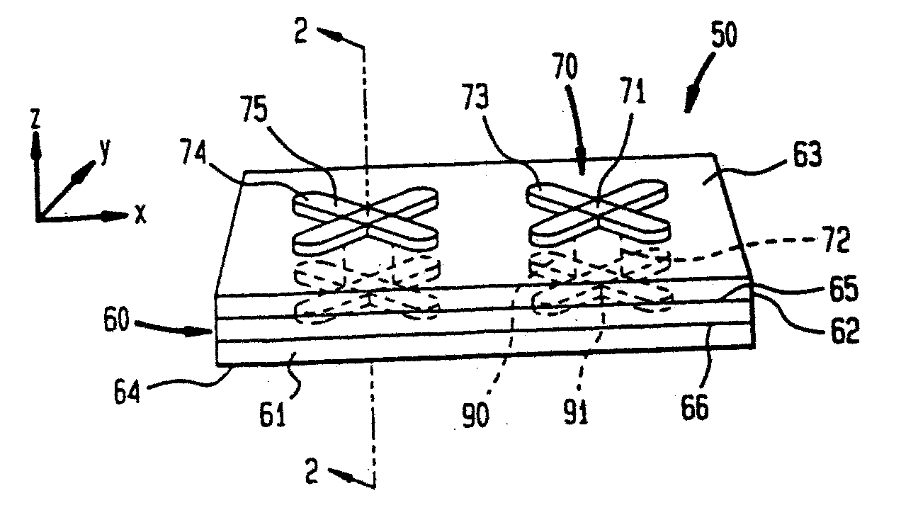
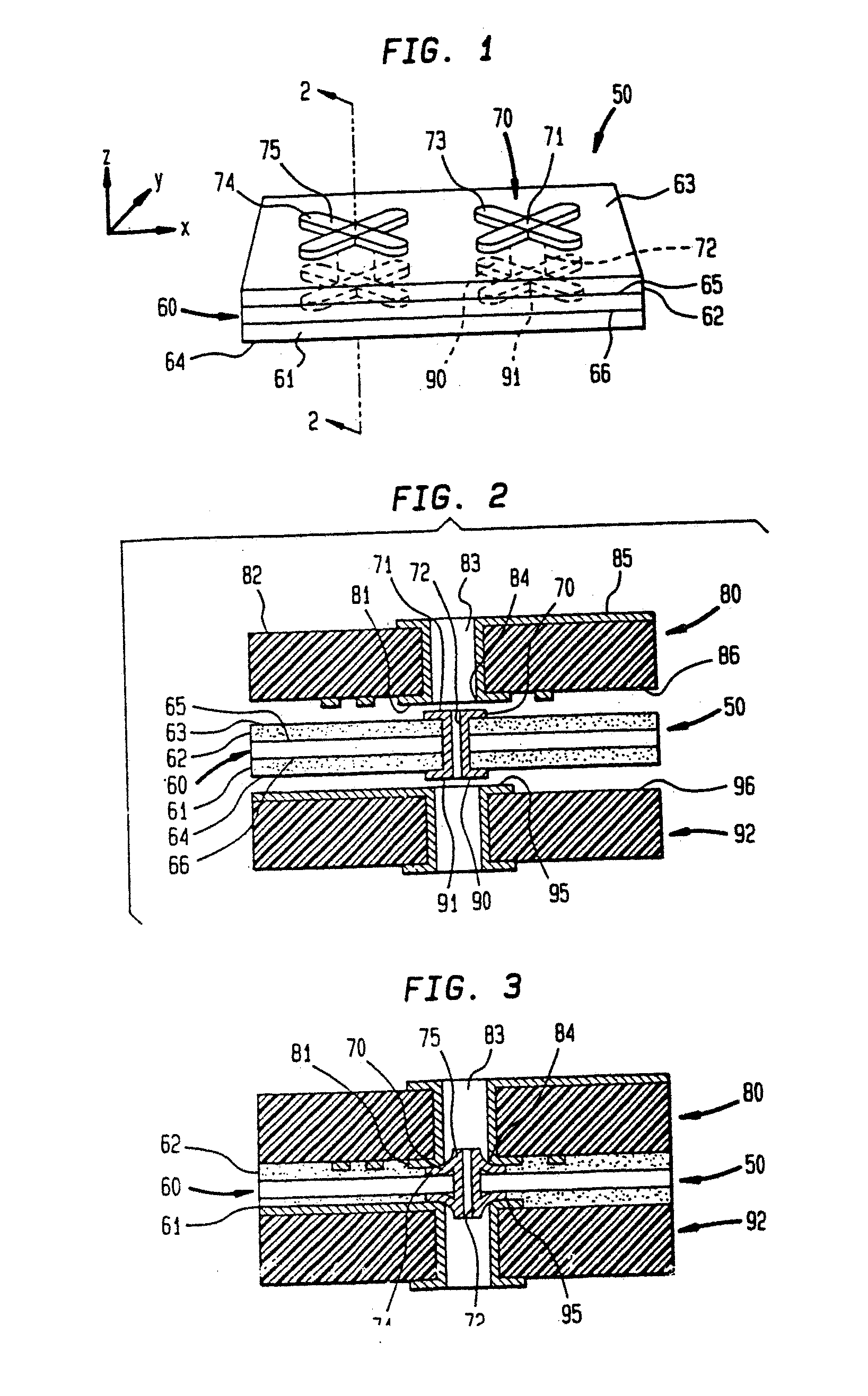
[0061] An interposer according to one embodiment of the invention, shown in FIG. 1, has a body 60 with a first major surface 65. The body 60 may be formed of a dielectric material such as polyimide, or of another non-conducting material. The top surface 65 of the body 60 extends in horizontal directions; i.e., directions x, y as shown in FIG. 1. A plurality of conductors 72 extend vertically, or in the z direction, into the body. In the preferred embodiment shown in FIG. 1, the conductors 72 extend through the body60. The conductors 72 may be elements formed by conductively plating vertical holes extending into the body 60 from the first surface 65. The conductors are formed of a structural conductive material such as copper, gold, tin or alloys thereof.

[0062] Each of the conductors 72 has a first end 71 positioned on or above the first major surface 65 of the body 60. Extending radially outward from the end 71 of the conductor is a contact 70. In the preferred embodiment shown in ...


PUM

PropertyMeasurementUnit
diameteraaaaaaaaaa
diameteraaaaaaaaaa
diameteraaaaaaaaaa

Abstract

A microelectronic interposer is made by providing a sacrificial layer over the surface of a planar body. Apertures are formed passing through the body and the sacrificial layer. A layer of an electrically conductive structural material is deposited in each of the apertures and over the sacrificial layer, proximate to each aperture to thereby form contacts. The sacrificial layer is removed leaving the contacts with outwardly flaring peripheral portions spaced vertically above the surface of the planar body.

Description

CROSS REFERENCE TO RELATED APPLICATIONS [0001] The present application is a divisional application of U.S. patent application Ser. No. 10 / 658,941, filed Sep. 10, 2003, which is a divisional application of U.S. patent application Ser. No. 10 / 200,941, filed Jul. 23, 2002, which is a divisional application of U.S. patent application Ser. No. 09 / 779,117, filed Feb. 8, 2001, which is a divisional application of U.S. patent application Ser. No. 08 / 989,305, filed Dec. 12, 1997, now U.S. Pat. No. 6,247,228, which claims the benefit of Provisional Patent Application No. 60 / 032,884, filed Dec. 13, 1996, which applications are hereby incorporated by reference in their entirety herein.BACKGROUND OF THE INVENTION [0002] The present invention relates to the field of electrical circuitry, and more particularly relates to layered circuit structures such as multilayer circuit boards, to components and methods utilized in fabrication of such structures and to methods of making the same. [0003] Electr...

Claims


Application Information

Patent Timeline
Patent Type & Authority Applications(United States)
IPC IPC(8): H05K1/00H01L23/498H01L23/538H01R12/51H05K1/03H05K1/11H05K3/46
CPCH01L23/49827Y10T29/49133H01R13/2414H01R23/72H01R43/0256H05K1/0272H05K1/036H05K1/056H05K1/116H05K3/0032H05K3/326H05K3/462H05K3/4623H05K3/4641H05K2201/0195H05K2201/0382H05K2201/0397H05K2201/09536H05K2201/09554H05K2201/096H05K2201/09827H05K2201/10378H05K2203/0554H05K2203/0582H05K2203/135H05K2203/308H01R12/523H01R12/714H01L2924/0002H01L23/5385Y10T29/49137Y10T29/49155Y10T29/49126Y10T29/49139Y10T156/1744Y10T29/49165H01L2924/00
Inventor DISTEFANO, THOMAS H.FJELSTAD, JOSEPH
Owner TESSERA INC
Learn More