
Apparatus and method for space-time block coding for increasing coding gain

a space-time block and coding technology, applied in the field of space-time block coding apparatus and methods in mobile communication systems, can solve the problems of inability to achieve the effect of improving coding gain, affecting the efficiency and reliability of data transmission on channels, and affecting the efficiency of data transmission in wireless channel environments of mobile communication systems

Inactive Publication Date: 2006-02-23
SAMSUNG ELECTRONICS CO LTD
View PDF8 Cites 25 Cited by
  • Summary
  • Abstract
  • Description
  • Claims
  • Application Information

AI Technical Summary

Benefits of technology

[0045] Accordingly, the present invention has been designed to substantially solve at least the above problems and / or disadvantages and to provide at least the advantages below. An object of the present invention is to provide a space-time block coding apparatus and method for improving coding gain in a mobile communication system with a plurality of antennas.
[0046] Another object of the present invention is to provide a space-time block coding apparatus and method for maximizing coding gain in a mobile communication system using a plurality of antennas, wherein vector symbols are rotated on a complex plane and the real and imaginary parts of the resulting new symbols xi+jyi are reconstructed, prior to transmission.
[0047] A further object of the present invention is to provide a space-time block coding apparatus and method providing phase rotation value for maximizing coding gain in a communication system using multiple antennas, wherein vector symbols are rotated on a complex plane and the real and imaginary parts of the resulting new symbols xi+jyi are reconstructed, prior to transmission.
[0048] A further object of the present invention is to provide a space-time block coding apparatus and method providing phase rotation value for maximizing coding gain in a communication system using even number of antennas, wherein vector symbols are rotated on a complex plane and the real and imaginary parts of the resulting new symbols xi+jyi are reconstructed, prior to transmission.
[0049] A further object of the present invention is to provide a space-time block coding apparatus and method providing phase rotation value for maximizing coding gain in a communication system using even number of multiple antennas, wherein vector symbols are rotated on a complex plane and the real and imaginary parts of the resulting new symbols xi+jyi are reconstructed, prior to transmission.

Problems solved by technology

A fundamental issue in communications is the efficiency and reliability with which data is transmitted on channels.
Generally, a transmission signal in a wireless channel environment of a mobile communication system inevitably experiences loss due to several factors such as multipath interference, shadowing, wave attenuation, time-variant noise, and fading.
The information loss causes a severe distortion to the transmission signal, degrading an entire system performance.
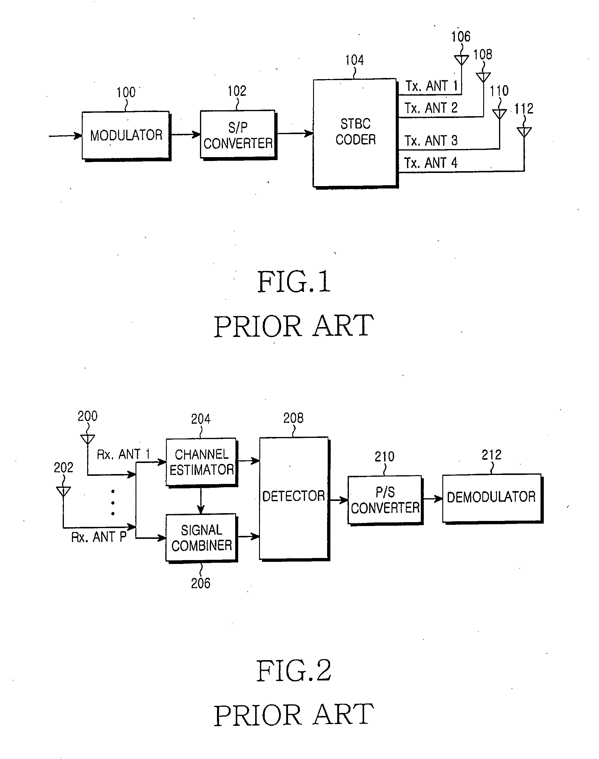
However, because four complex symbols are transmitted for eight time intervals, the Tarokh STBC scheme decreases the data rate by half.
In addition, because it takes eight time intervals to completely transmit one block with four complex symbols, reception performance is degraded due to channel changes within the block over a fast fading channel.
That is, the transmission of complex symbols through four or more Tx antennas requires 2N time intervals for N symbols, causing a longer latency and a decrease in data rate.
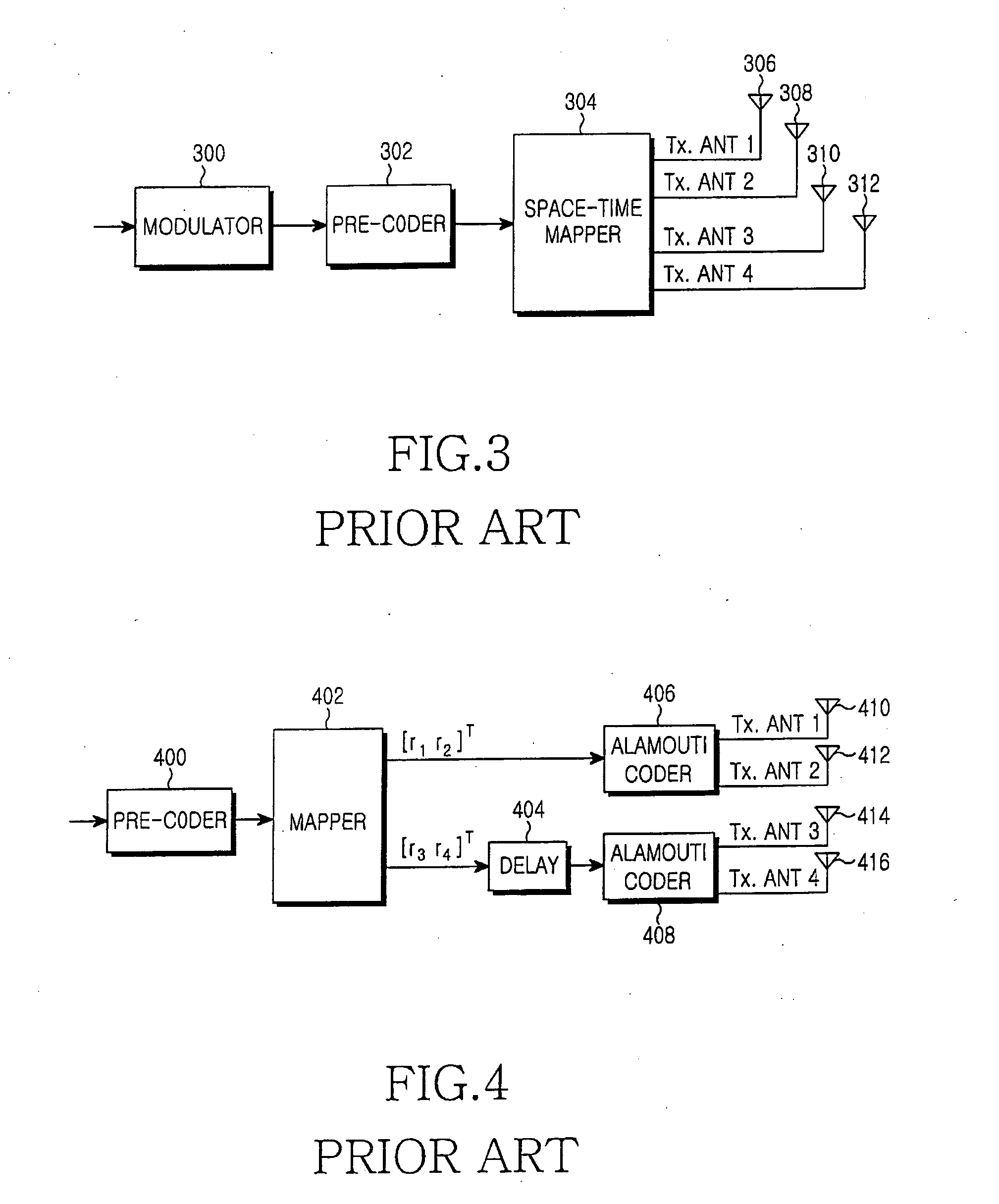
However, all the approaches described above suffer from high decoding complexity relative to the Alamouti scheme that allows linear decoding of transmitted symbols, and thus continual efforts have been made to further decrease the decoding complexity.
In an actual simulation, however, the use of this value degrades the system performance.

Method used


Image

  • Apparatus and method for space-time block coding for increasing coding gain
  • Apparatus and method for space-time block coding for increasing coding gain
  • Apparatus and method for space-time block coding for increasing coding gain

Examples


Embodiment Construction

[0063] Preferred embodiments of the present invention will be described in detail herein below with reference to the accompanying drawings. In the following description, well-known functions or constructions are not described in detail since they would obscure the invention in unnecessary detail.

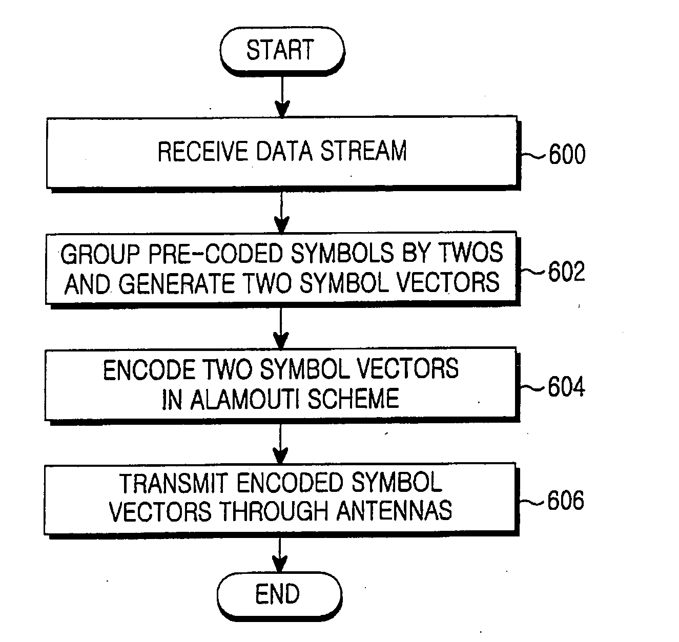
[0064] Generally, the present invention is intended to provide a space-time block coding apparatus in a transmitter having a plurality of antennas, e.g., four antennas are assumed in the following embodiments, in a communication system. An input symbol stream is transmitted through a plurality of Tx antennas in a predetermined method in order to maximize coding gain of a space-time block coding.

[0065] A transmitter in a communication system according to the present invention uses four antennas. When new value xi+jyi is obtained by multiplying a symbol vector by ejθ, θ being a phase rotation angle, it can be checked that the calculation of the space-time block coding by using the design rul...


PUM


Abstract

A space-time block coding apparatus and method in a transmitter with four transmit antennas in a system using a space-time block coding scheme, a pre-coder pre-codes an input symbol sequence by multiplying the input symbol sequence by ejθ, θ being a phase rotation angle, in case of QPSK in range of 0≦θ≦90, 23.5≦θ≦24.5, or 65.5≦θ≦66.5, in case of 16QAM in range of 0≦θ≦90, 15.5≦θ≦17.5 or 72.5≦θ≦74.5, the pre-coded symbol sequence being reconstructed to have real and imaginary parts. A mapper generates symbol vectors by recombining the real and imaginary parts of the pre-coded symbol sequence in an interleaving scheme. A plurality of Alamouti coders encodes the symbol vectors in an Alamouti scheme and transmits the encoded symbol vectors through corresponding transmit antennas.

Description

PRIORITY [0001] This application claims priority under 35 U.S.C. § 119 to an application entitled “Apparatus And Method For Space-Time Block Coding For Increasing Coding Gain” filed in the Korean Intellectual Property Office on Aug. 17, 2004 and assigned Ser. No. 2004-0064900, the contents of which are herein incorporated by reference. BACKGROUND OF THE INVENTION [0002] 1. Field of the Invention [0003] The present invention relates generally to a transmit (Tx) antenna diversity apparatus and method in a mobile communication system, and in particular, to a space-time block coding apparatus and method in a mobile communication system using multiple antennas in order to maximize a coding gain. [0004] 2. Description of the Related Art [0005] A fundamental issue in communications is the efficiency and reliability with which data is transmitted on channels. As future-generation multimedia mobile communications require high-speed communication systems capable of transmitting a variety of i...

Claims


Application Information

Patent Timeline
IPC IPC(8): H04K1/10H04L1/02
CPCH04L1/0071H04L1/0637H04L1/0625H04B7/06
Inventor CHAE, CHAN-BYOUNGYUN, SUNG-RYULJEONG, HONG-SILROH, WON-ILPARK, DONG-SEEKJOO, PAN-YUHOH, JEONG-TAEKO, KYUN-BYOUNG
Owner SAMSUNG ELECTRONICS CO LTD
Learn More