
Computer-implemented methods for generating input for a simulation program or generating a simulated image of a reticle

Active Publication Date: 2006-02-16
KLA TENCOR CORP
View PDF17 Cites 49 Cited by
  • Summary
  • Abstract
  • Description
  • Claims
  • Application Information

AI Technical Summary

Benefits of technology

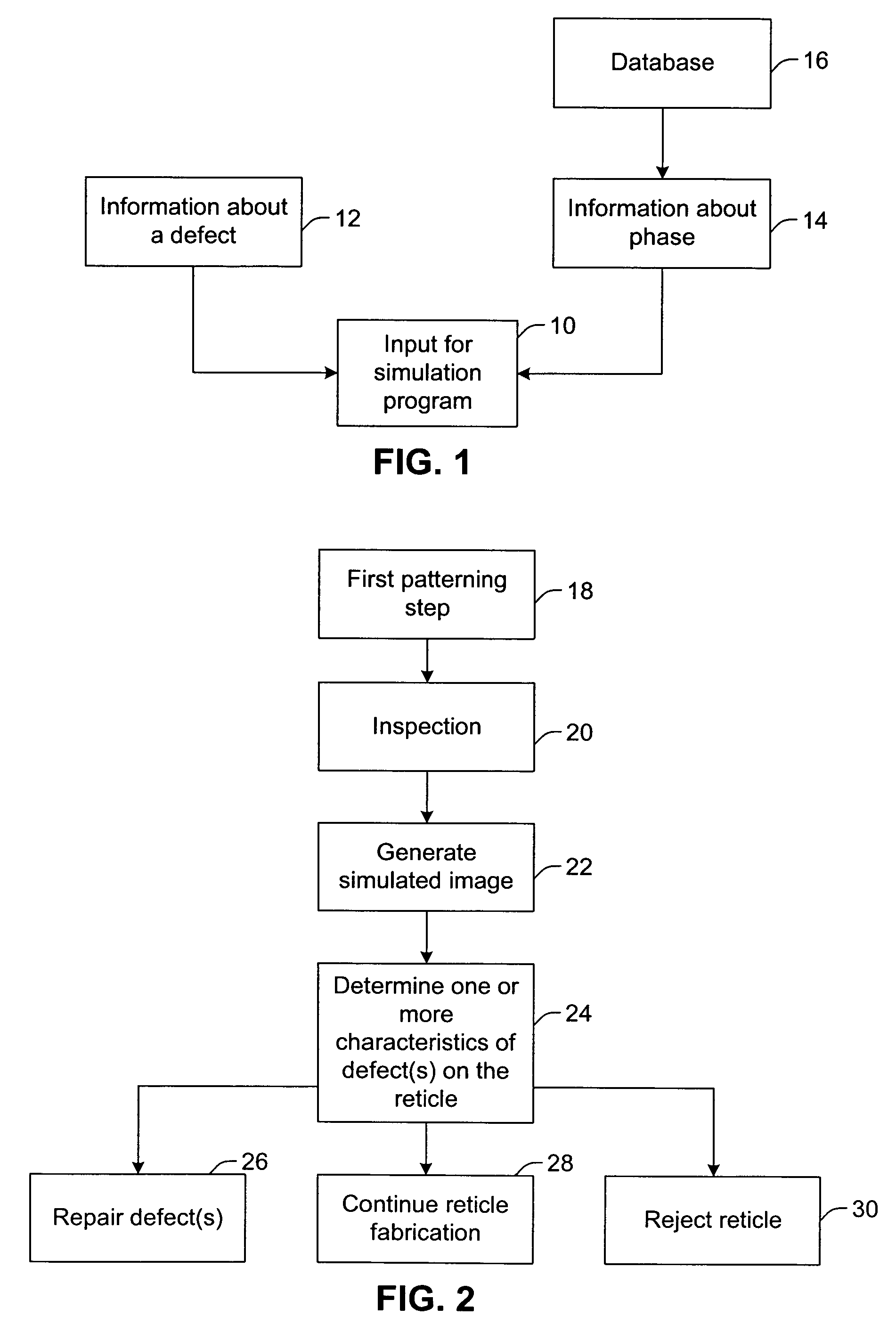
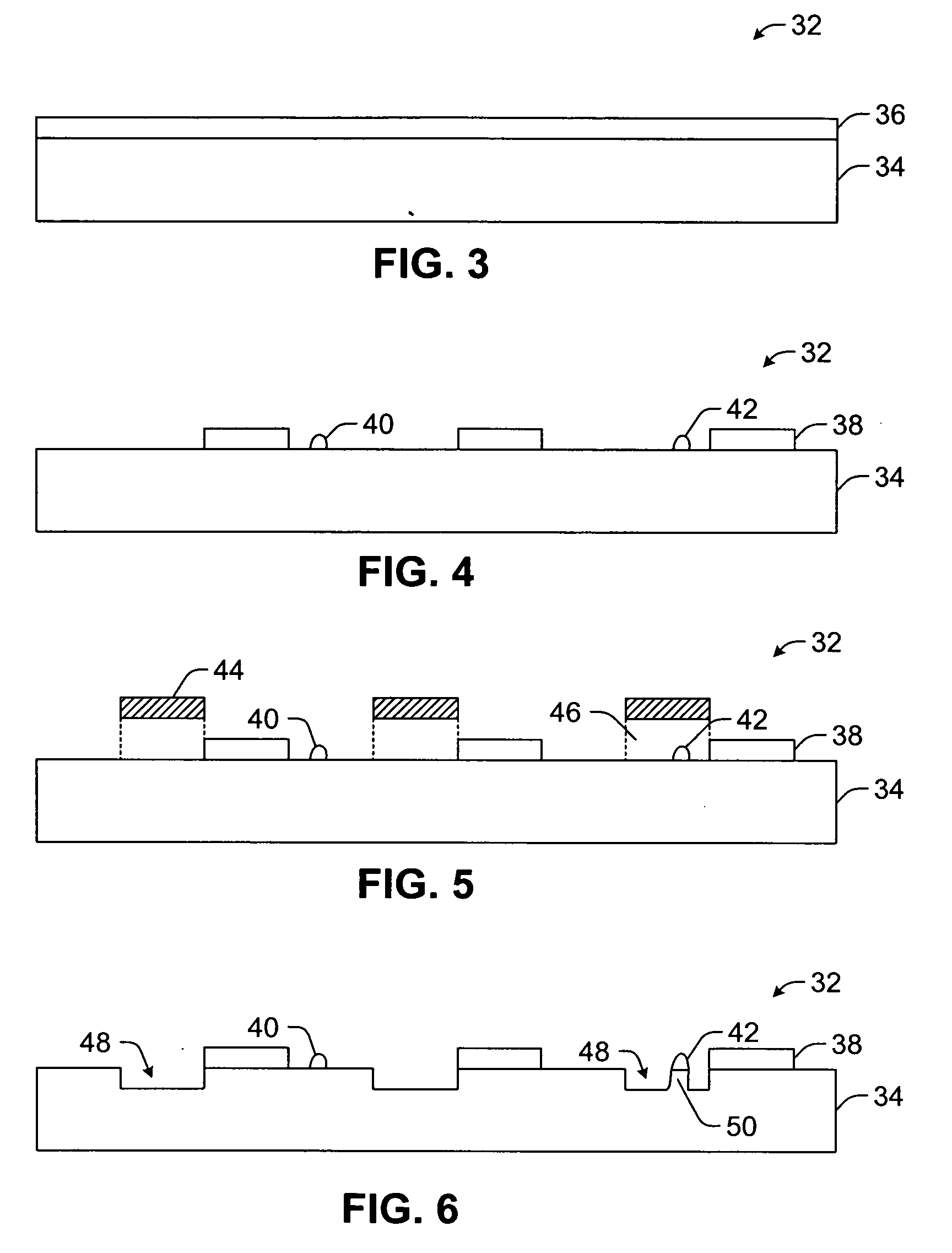
[0017] It is advantageous to determine the quality of a reticle as early as possible in the mask making process in order to minimize cycle time and manufacturing costs. However, many resolution enhancement techniques (RETs) make use of phase shifting reticles, which are fabricated using multiple patterning and processing steps as described above. These multiple steps add significant cycle time and manufacturing expense. It is, therefore, desirable to determine the quality of a reticle before the completion of all patterning and process steps so as to avoid adding further value to the reticle if a fatal defect exists due to an earlier patterning / process step. This determination can be difficult since a defect generated in the first patterning step may or may not have a phase component that has not yet been added to the reticle since this will occur in later patterning / process steps.
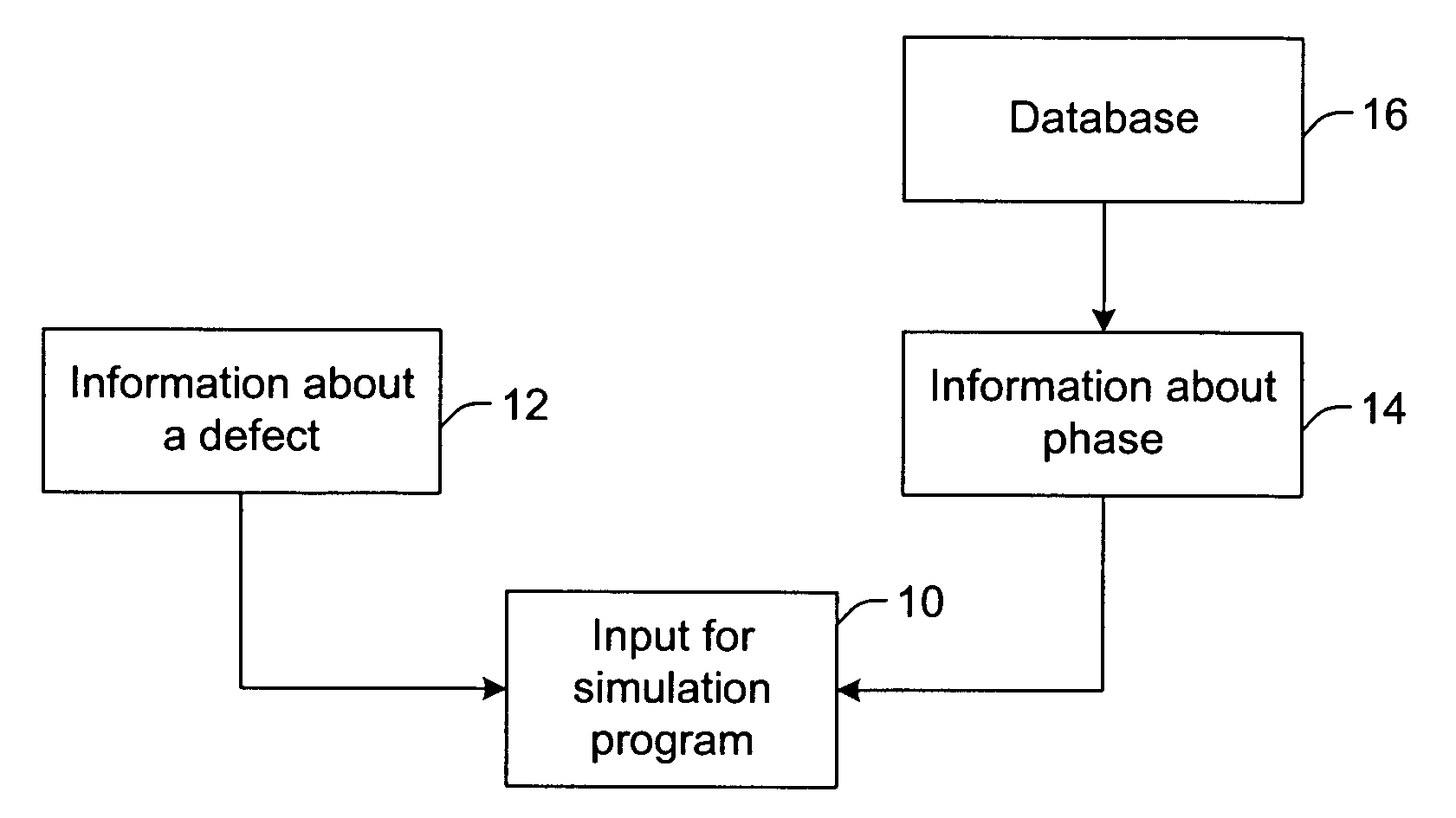
[0018] The methods described herein make use of the second level patterning data to aid in the determination of the location of phase areas on the reticle, which can be fed forward to an optical lithography simulation program. Furthermore, based upon a priori knowledge of the mask making process and the defect's location relative to the phase pattern information, phase information can be assigned to the defect to improve the accuracy of the simulation results. This method can be implemented as a component of a multi-level database inspection in which the phase information from the database is overlaid with the optical image of the defect and stored to a file that is used as input to the optical simulation program.

Problems solved by technology

These multiple steps add significant cycle time and manufacturing expense.
This determination can be difficult since a defect generated in the first patterning step may or may not have a phase component that has not yet been added to the reticle since this will occur in later patterning / process steps.

Method used


Image

  • Computer-implemented methods for generating input for a simulation program or generating a simulated image of a reticle
  • Computer-implemented methods for generating input for a simulation program or generating a simulated image of a reticle
  • Computer-implemented methods for generating input for a simulation program or generating a simulated image of a reticle

Examples


Embodiment Construction

[0042] As used herein, the term “reticle” refers to a reticle or a mask. A reticle generally includes a transparent substrate such as glass, borosilicate glass, and fused silica having a layer of opaque material formed thereon. A reticle may include additional materials formed under the opaque material such as an adhesion layer. In addition, a reticle may include additional materials formed on top of the opaque material such as a bottom anti-reflective coating, a resist, and a top anti-reflective layer. The opaque material layer may be patterned to form opaque regions on the substrate. Alternatively, the opaque regions may be replaced by regions etched into the transparent substrate. A reticle, as described herein, may or may not include a pellicle.

[0043] Different types of reticles include, but are not limited to, a clear-field reticle, a dark-field reticle, a binary reticle, a phase-shift mask (PSM), an alternating PSM, an attenuated or halftone PSM, and a ternary attenuated PSM,...


PUM


Abstract

Various computer-implemented methods are provided. One computer-implemented method for generating input for a simulation program includes combining information about a defect detected on a partially fabricated reticle with information about phase assigned to an area of the reticle proximate to the defect. The phase is to be added to the reticle on a level other than a level on which the defect is formed. The defect is detected on the reticle prior to addition of the phase to the reticle. Another computer-implemented method includes generating a simulated image of a defect on a reticle using information about the defect generated by inspection of one level of the reticle in combination with information about a different level on the reticle.

Description

PRIORITY CLAIM [0001] This application claims priority to U.S. Provisional Application No. 60 / 589,864 entitled “Computer-Implemented Methods for Generating Input for a Simulation Program or Generating a Simulated Image of a Reticle,” filed Jul. 21, 2004, which is incorporated by reference as if fully set forth herein.BACKGROUND OF THE INVENTION [0002] 1. Field of the Invention [0003] The present invention generally relates to computer-implemented methods for generating input for a simulation program or generating a simulated image of a reticle. Certain embodiments relate to a computer-implemented method that includes combining information about a defect detected on a partially fabricated reticle with information about phase assigned to an area of the reticle proximate to the defect. [0004] 2. Description of the Related Art [0005] The following description and examples are not admitted to be prior art by virtue of their inclusion in this section. [0006] Semiconductor fabrication proc...

Claims


Application Information

Patent Timeline
IPC IPC(8): G06F17/50G03F1/00
CPCG03F1/0092G03F1/14G06F2217/12G03F1/84G06F17/5009G03F1/72G06F30/20G06F2119/18Y02P90/02
Inventor ZURBRICK, LARRY STEVENLEHON, HAROLD WILLIAM
Owner KLA TENCOR CORP
Learn More