
Apicoaortic conduit connector and method for using

Inactive Publication Date: 2006-02-16
CORSYNERGY
View PDF6 Cites 75 Cited by
  • Summary
  • Abstract
  • Description
  • Claims
  • Application Information

AI Technical Summary

Benefits of technology

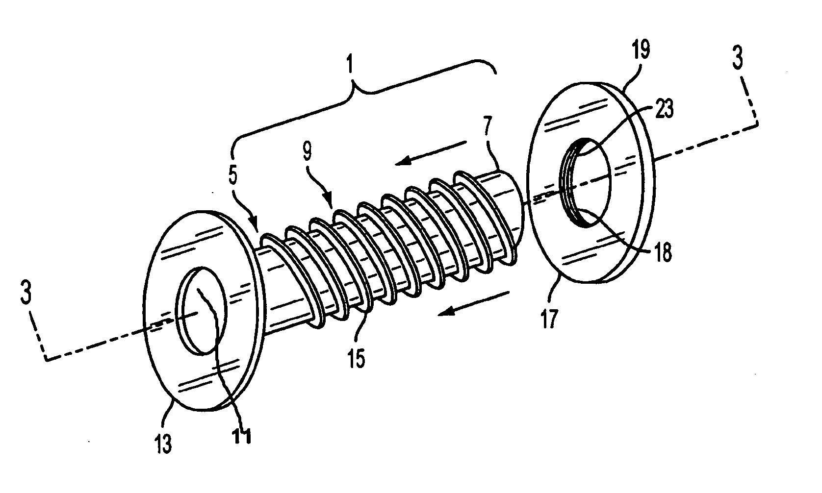
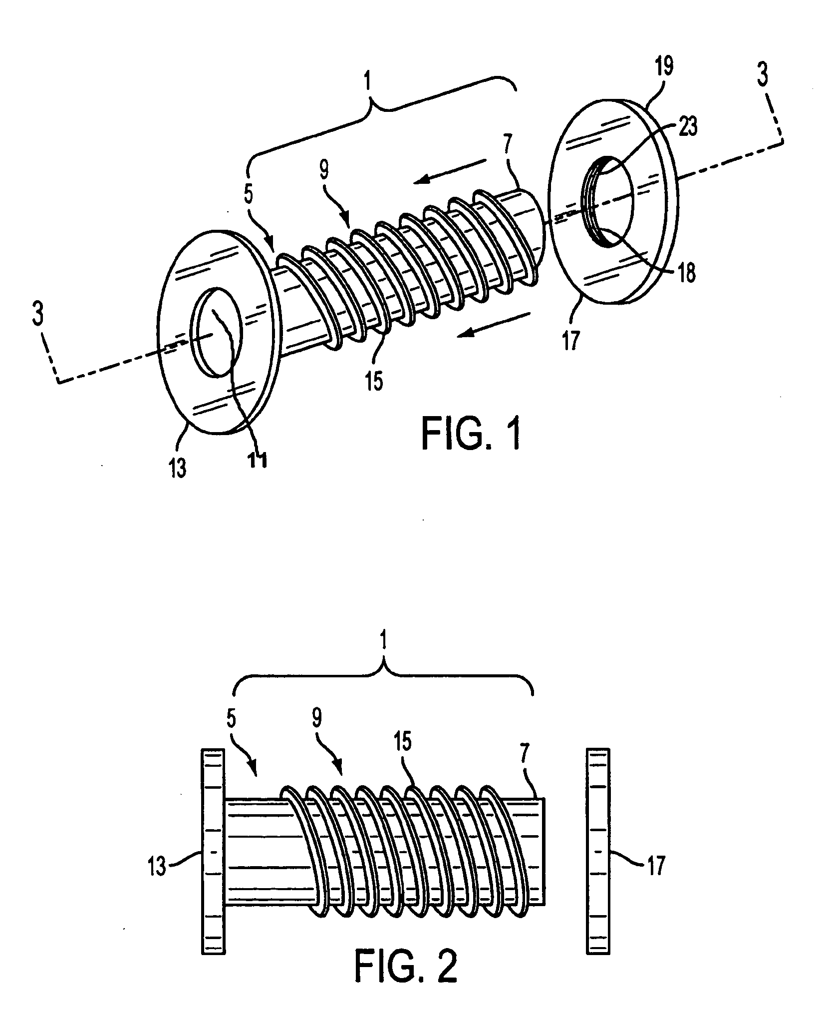
[0007] This invention describes an improved apparatus and method for AAC insertion that will significantly improve and simplify the insertion of a graft into the beating cardiac apex, making AAC insertion far more attractive. By creating a second outflow tract off pump, the detrimental effects of both CPB and global cardiac ischemia are avoided. Additionally, the conduction system is avoided as are the native coronary arteries and grafts from previous surgical revascularization. A small size valve (19 to 21 mm) for typical adult body surface areas is usually adequate, as the effective postoperative orifice is the sum of the native and prosthetic aortic valves. Further, valved conduit failure is far less likely with the availability of newer generation biologic valves.
[0010] Use of this new apparatus and method will significantly improve the ease and safety of AAC insertion. As persons of ordinary skill would readily appreciate, this method can also be used in a minimally invasive, endoscopically assisted approach.

Problems solved by technology

However, the AAC insertion procedure has been poorly accepted, primarily because of early valve failures using first-generation bioprostheses as well as the success of direct LVOTO repair and aortic valve replacement.
Further, the AAC insertion operation, with or without cardiopulmonary bypass, has not been as technically straightforward as direct aortic valve replacement.
While off-pump cases have been described, they can be technically difficult.

Method used


Image

  • Apicoaortic conduit connector and method for using
  • Apicoaortic conduit connector and method for using
  • Apicoaortic conduit connector and method for using

Examples


first embodiment

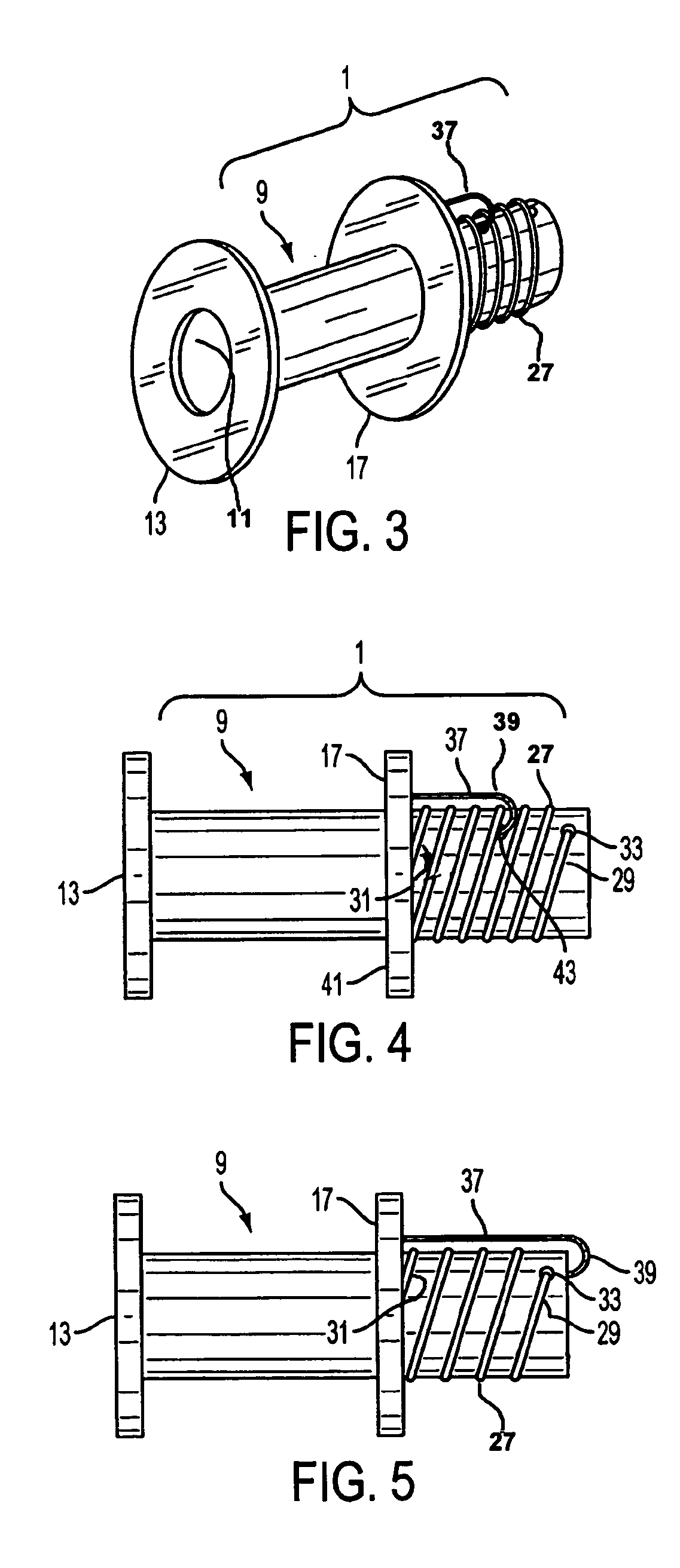
[0026] In accordance with one method for using the connector of the invention, a needle is passed through the apex and into the left ventricle. A guide wire is then inserted into the opening and, following dilation of the opening, an occlusion device is threaded over the wire and into the left ventricle and deployed. The occlusion device may include known occlusion devices such as an occlusion balloon, the Guidant Heartstring™ disclosed at http: / / www.guidant.com / products / producttemplates / cs / heartstring.shtml, or the Baladi inverter, disclosed in U.S. Pat. Nos. 5,944,730 and 6,409,739. A ventricular coring device is then threaded in-line over the occlusion device and a core of ventricular muscle is removed at the apex. In addition to known coring techniques, an annular contact laser may be used to vaporize the tissue along the perimeter of the core. The cored tissue may then be removed according to known methods. According to a further alternative embodiment, a contact laser may be u...

second embodiment

[0027] once the flange has been introduced into the ventricle and pulled back to engage the interior ventricle wall, release device 37 is released, allowing biasing device 27 to force the external ring 17 against the external wall of the apex. According to a further aspect of this embodiment of the invention, threads on the inside diameter of external ring may be made to engage threads oh the outer surface of conduit 1 to further secure external ring against the wall of the apex.

[0028] Once the connector is firmly in place, the occlusion device is withdrawn. The connector is then clamped shut while its free end is connected to the graft which terminates, or which will terminate, at the aorta.


PUM


Abstract

An improved apparatus and method for AAC insertion including a new AAC connector having a threaded or partially threaded body. The AAC connector has a flexible flange situated at one end that is soft and thin enough to bend backwards so that it can be pushed through an opening made in the apex, but rigid enough to flex back to its original position and hold its shape once it enters the interior of the left ventricle. A second ring is also provided that is adapted to be deployed over the body of the connector and against the exterior wall of the apex.

Description

FIELD OF INVENTION [0001] This invention relates to devices and methods for creating an alternative conduit between the left ventricle and the aorta to create a double-outlet left ventricle. BACKGROUND [0002] Construction of an alternative conduit between the left ventricle and the aorta (an apicoaortic conduit, or AAC) to create a double-outlet left ventricle (LV) has been successfully employed to treat a variety of complex congenital LV outflow obstruction (fibrous tunnel obstruction, aortic annular hypoplasia, tubular hypoplasia of the ascending aorta, and patients with diffuse septal thickening, severe LV hypertrophy and a small LV cavity) as well as adult-onset aortic stenosis in patients with complicating preoperative conditions (previous failed annular augmentation procedures, previous infection, previous CABG with patent anterior internal mammary artery grafts, and a porcelain ascending aorta). [0003] However, the AAC insertion procedure has been poorly accepted, primarily b...

Claims


Application Information

Patent Timeline
IPC IPC(8): A61F2/06
CPCA61F2/064
Inventor VASSILIADES, THOMAS A.
Owner CORSYNERGY
Learn More