Hidden fire escape ladder system

Inactive Publication Date: 2012-06-28
BARBARA JAMES
View PDF0 Cites 1 Cited by
  • Summary
  • Abstract
  • Description
  • Claims
  • Application Information

AI Technical Summary

Benefits of technology

[0005]In accordance with the invention, a fire escape ladder device that can be anchored to a window, or permanently installed under a window and concealed within a wall cavity for quick and reliable deployment comprises a series of rigid rungs. The rungs are supported between a pair of flexible and bendable side supports. The rungs are provided with spring-loaded extendable arms. Alternatively, a spring hinge or other similar self opening mechanism may be used. The rungs can be treated with anti-slip tape, ribbed applications, or abrasive type paint or other material to prevent slipping. The arms are held proximate to their respective rung by locking pins, which are slidably mounted in holes in the rung and arms. The extendable arms may be coated, or capped with a PVC type material, or rubber type coating that protects the house from scratching or marring the house. The pins are connected to a common line secured to an anchor. The line is shorter than the corresponding portion of the flexible and bendable side supports.
[0007]When the fire escape ladder is tossed out the window during an emergency situation, the line pulls the pins from the holes in the rungs and arms. Removal of the locking pins releases the arms allowing the springs to cause them to extend from the rungs, leaving the rungs supported by flexible and bendable side supports. The arms may also be held proximate to their respective rung by stiff / rigid wire supports that extend upward from the bottom of the storage box through the corresponding holes in the rungs. In contrast, the flexible and bendable side supports are affixed to both sides of the rungs via metal clamps in such a fashion that the rungs remain in a fixed position with respect to the side supports. Accordingly, the rungs remain secure for a person to descend while being supported away from the side of the house to improve the ease and safety of climbing.
[0009]Furthermore the inventive system can be completely concealed within a wall cavity and extended upward through an opening in the window or the interior wood window sill, thus allowing furniture or other items to be used under the window overcoming the flaws of other permanently installed interior permanent fire escape ladders. Another benefit of the fire escape ladder is by using a U-channel rung to house the arm or standoff, a longer extendable arm is used thus providing a greater distance from the house to the rung allowing more room for hand and foot holds providing a safer decent down the ladder.

Problems solved by technology

If such a stiff wire is used, it may be quite short, for example approximately the height of the box containing the fire escape ladder system.

Method used


Image

  • Hidden fire escape ladder system
  • Hidden fire escape ladder system
  • Hidden fire escape ladder system

Examples


Embodiment Construction

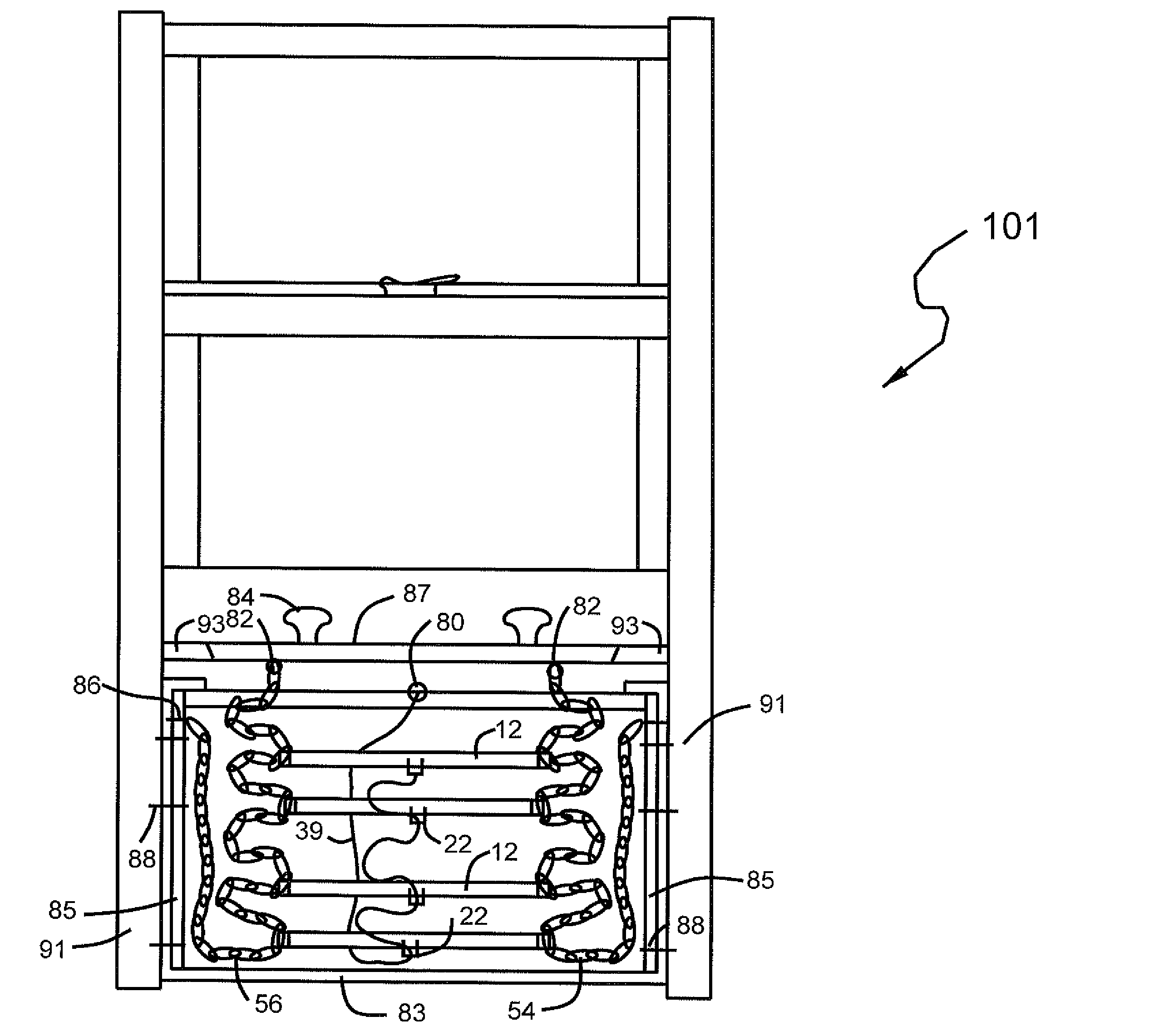
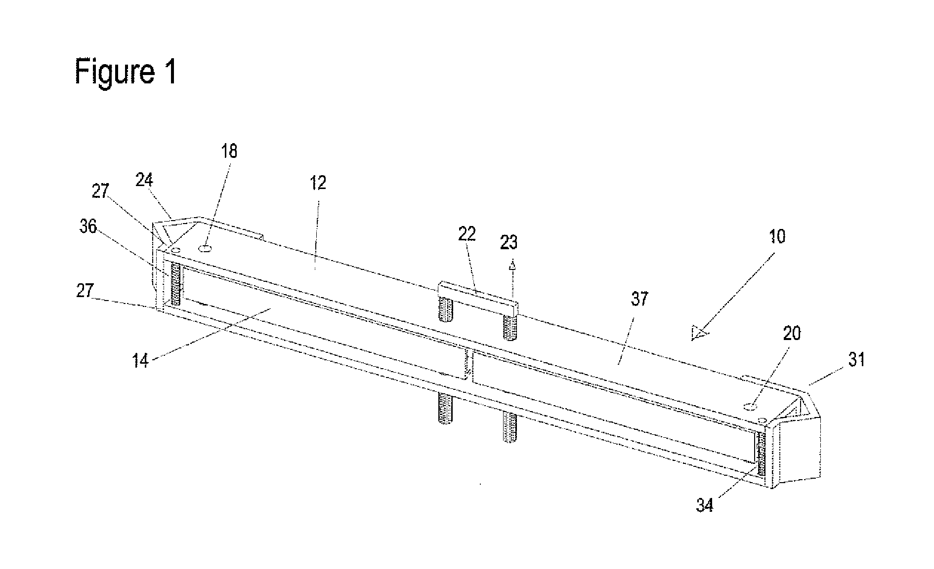
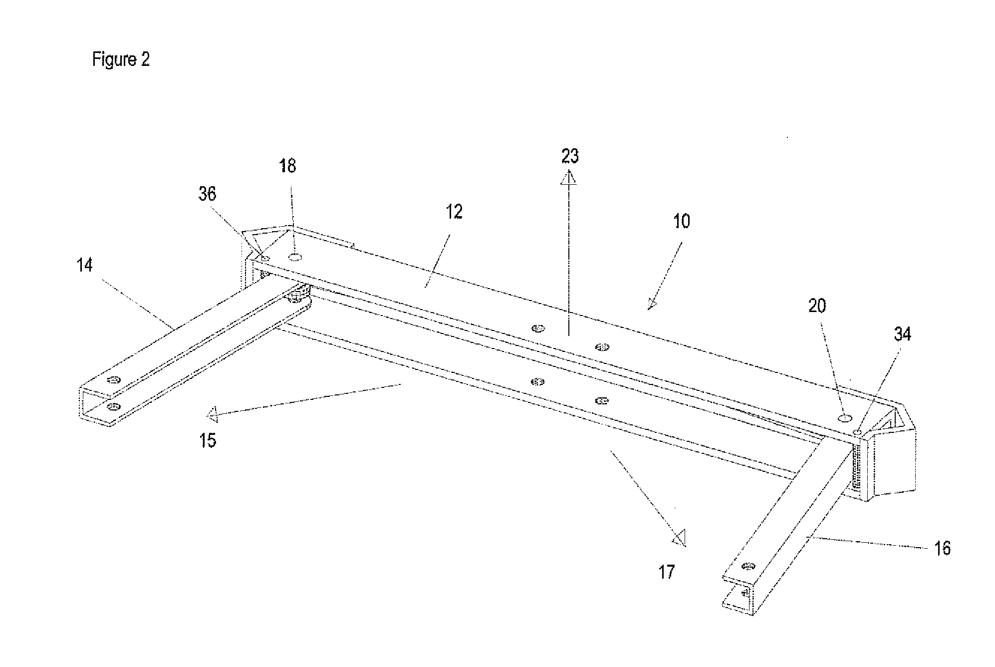
[0025]Referring to FIGS. 1 and 1a, the inventive fire escape ladder device 10 comprises a plurality of rungs 12, one of which is illustrated in FIG. 1. Rungs may be ribbed, or may have an anti-slip tape, or abrasive paint applied to the top of the rung to prevent slipping of the rung. Rungs 12 are each supported at their ends by a pair of chains or other supports as described below. Rungs 12 are generally rectangular-shaped in cross-section and made of a rigid metal, such as aluminum or steel car which PVC, or other appropriate material. Each rung 12 is provided with two extendable arms 14 and 16, which are long enough to serve as standoffs for maintaining a gap between the ladder 10 and the side of a building after deployment of the ladder 10. Arms 14 and 16 have holes 15 drilled therein. The extendable arms may have a rubberized coating or pvc caps applied to the ends to prevent damage to the house. Arms 14 and 16 are rotatably mounted on pins 18 and 20. Pins 18 and 20 are frictio...


PUM


Abstract

Apparatus for escaping from a building through a window, comprises a plurality of rungs having first and second ends. A first side support is coupled to the first ends of the rungs. The first side support has an upper end. A second side support is coupled to the second ends of the rungs. The first side support has an upper end. A securement assembly is coupled to the wall of a building adjacent a window for providing egress. A first securement secures the upper end of the first side support to the securement member. A second securement secures the upper end of the second side support to the securement member. A plurality of first arms are each positioned proximate the first ends of a respective one of the rungs and are each moveably mounted to go from a retracted position to an extended position. A plurality of first arms are each positioned proximate the first ends of a respective one of the rungs and are each moveably mounted to go from a retracted position to an extended position.

Description

CROSS REFERENCE TO RELATED APPLICATIONS[0001]This application claims the benefit of my copending U.S. patent application Ser. No. 11 / 064,424, filed Feb. 23, 2005 and its parent U.S. patent application Ser. No. 10 / 641,673, filed Aug. 15, 2003, and provisional patent application No. 60 / 485,916 filed Jul. 9, 2003, the disclosures of which are hereby incorporated herein by reference thereto.TECHNICAL FIELD[0002]The invention relates to apparatus and methods for providing a readily accessible fire escape ladder in the context of new construction and replacement window installations, including hidden and external locker retrofits.STATEMENT REGARDING FEDERALLY SPONSORED RESEARCH OR DEVELOPMENT[0003](Not applicable)BACKGROUND OF THE INVENTION[0004]Today, externally applied fire exits are used to escape from large buildings. Most homes, however, do not have a means of escape, particularly from the second or higher floors. People located, for example, on the second floor of a private wood fra...

Claims


Application Information

Patent Timeline
IPC IPC(8): E06C9/14
CPCA62B1/00E06C9/14E06B7/28
Inventor BARBARA, JAMES
Owner BARBARA JAMES
Why Eureka
Try Eureka