
Modified backoff mechanism for wireless networks

a backoff mechanism and wireless network technology, applied in the direction of wireless commuication services, network traffic/resource management, transmission, etc., can solve the problems of inability to detect collisions while transmitting, inconvenient use of collision detection schemes, and use of collision avoidance approaches instead of collision detection schemes

Inactive Publication Date: 2006-02-16
NORTEL NETWORKS LTD
View PDF1 Cites 70 Cited by
  • Summary
  • Abstract
  • Description
  • Claims
  • Application Information

AI Technical Summary

Benefits of technology

[0015] In accordance with another aspect of the present invention there is provided a computer-readable medium storing instructions which, when executed by a station in a wireless network, cause the station to: for each of a plurality of attempted retransmissions: increase the size of a group of delay periods such that the group grows at a rate that is less than exponentially with the number of attempted retransmissions; and select a delay period from the group of delay periods for use in scheduling a retransmission over the wireless network.

Problems solved by technology

Wireless stations are generally unable to detect collisions while transmitting, since a transmitting station's receiving antenna cannot hear any signal but the station's own transmitted signal.
For this reason, the collision avoidance approach is used instead of the collision detection scheme is not suitable for use with wireless LANs.
When the proposed transmitter attempts to retransmit, it is of course possible that the retransmission will not be possible because the medium has once again become busy.
Significant delays may for example occur when the transfer of a large file by one station causes a relatively large amount of collisions and exponential backoff at other stations.
Extended backoff delays tend to cause outgoing messages to become backlogged at a station, which may result in increased competition for the transmission medium between stations.
As the number of stations connected to a wireless network increases, delays may be exacerbated due to the overall increase in volume of data communications.

Method used


Image

  • Modified backoff mechanism for wireless networks
  • Modified backoff mechanism for wireless networks
  • Modified backoff mechanism for wireless networks

Examples


Embodiment Construction

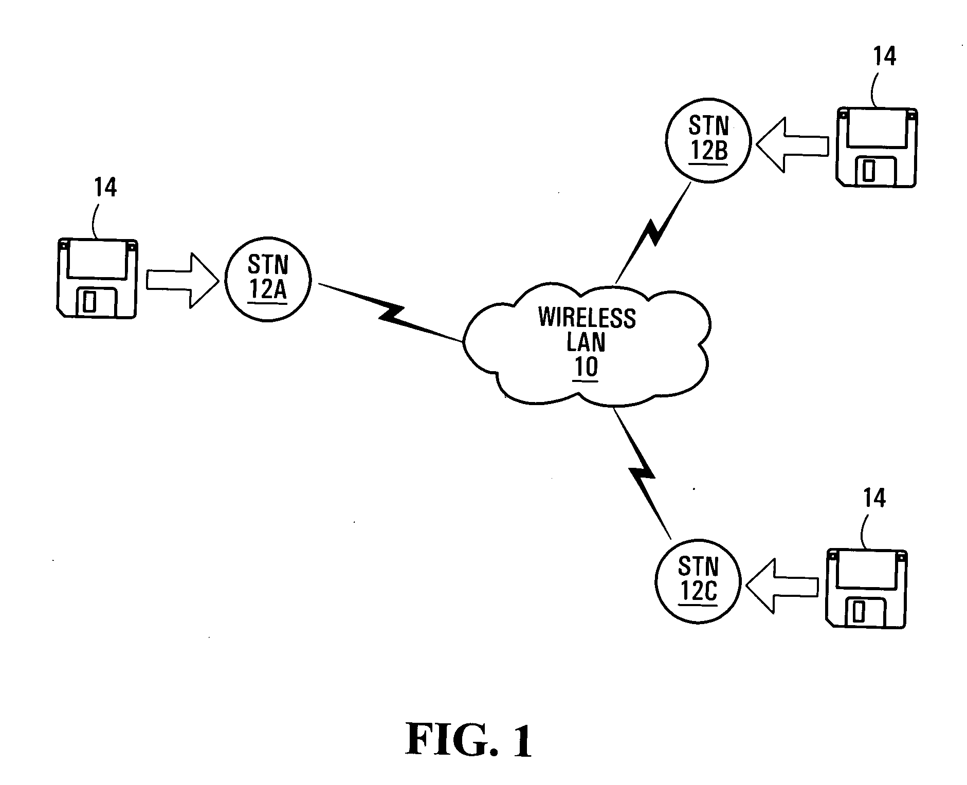
[0021]FIG. 1 illustrates a wireless local area network (LAN) 10 including a number of stations 12A, 12B and 12C (referred to generically and cumulatively as station(s) 12). The stations 12 may be portable computers, portable digital assistants, VLAN mobile (i.e. WLAN cordless) handsets or other computing devices which are capable of intercommunication over the common wireless medium provided by the LAN 10. The wireless LAN 10 in the present embodiment operates in accordance with a modified version the IEEE 802.11 protocol, as will be described.

[0022] Each station 12 in the wireless LAN 10 accesses the shared medium in accordance with a modified version of the Carrier Sense Multiple Access / Collision Avoidance (CSMA / CA) protocol. The modified CSMA / CA protocol is the same as the CSMA / CA protocol employed in the IEEE 802.11 standard, except that a different backoff delay mechanism is used. The CSMA / CA protocol may for example be executed by a LAN controller (not shown) in each station....


PUM


Abstract

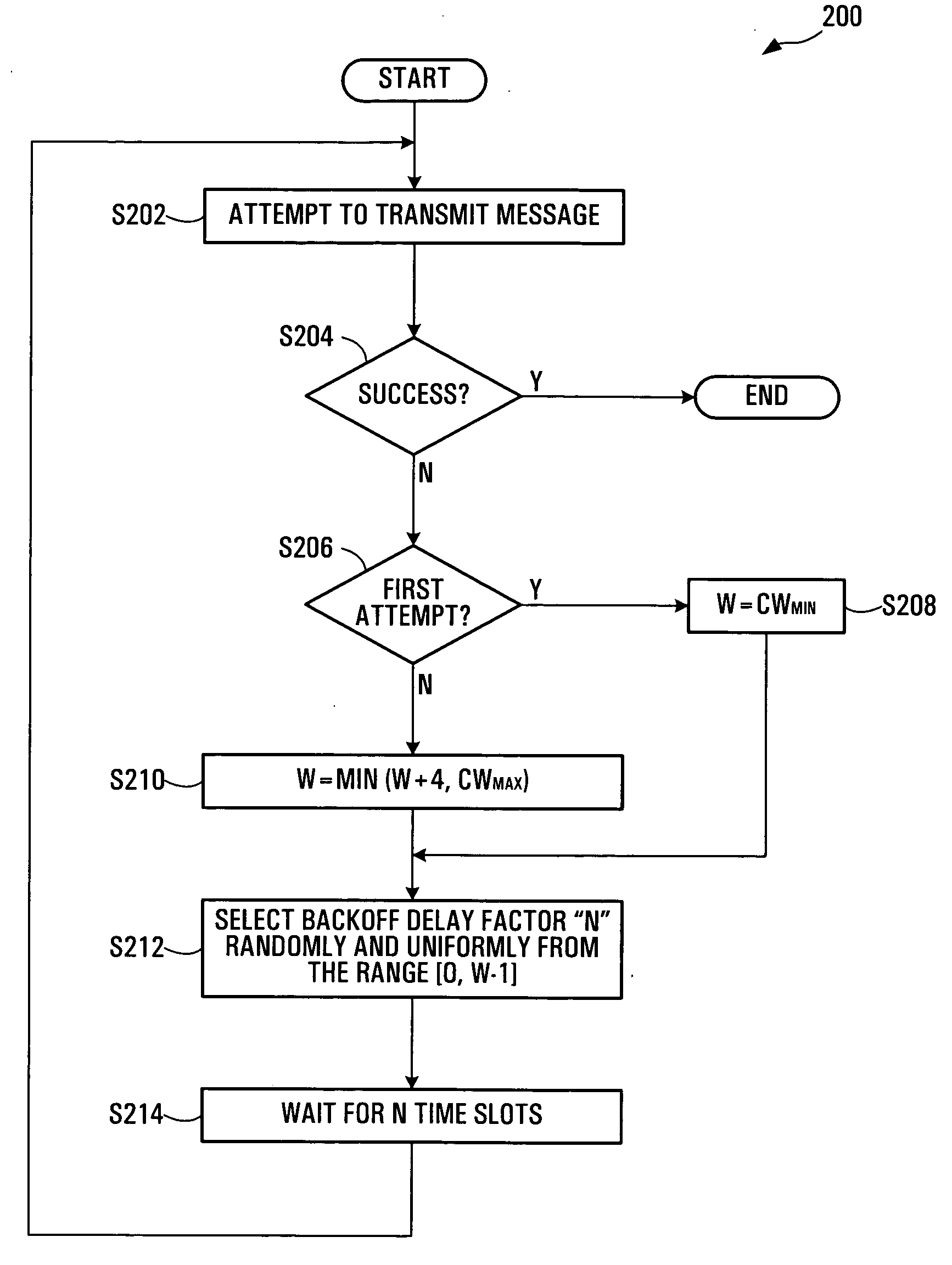
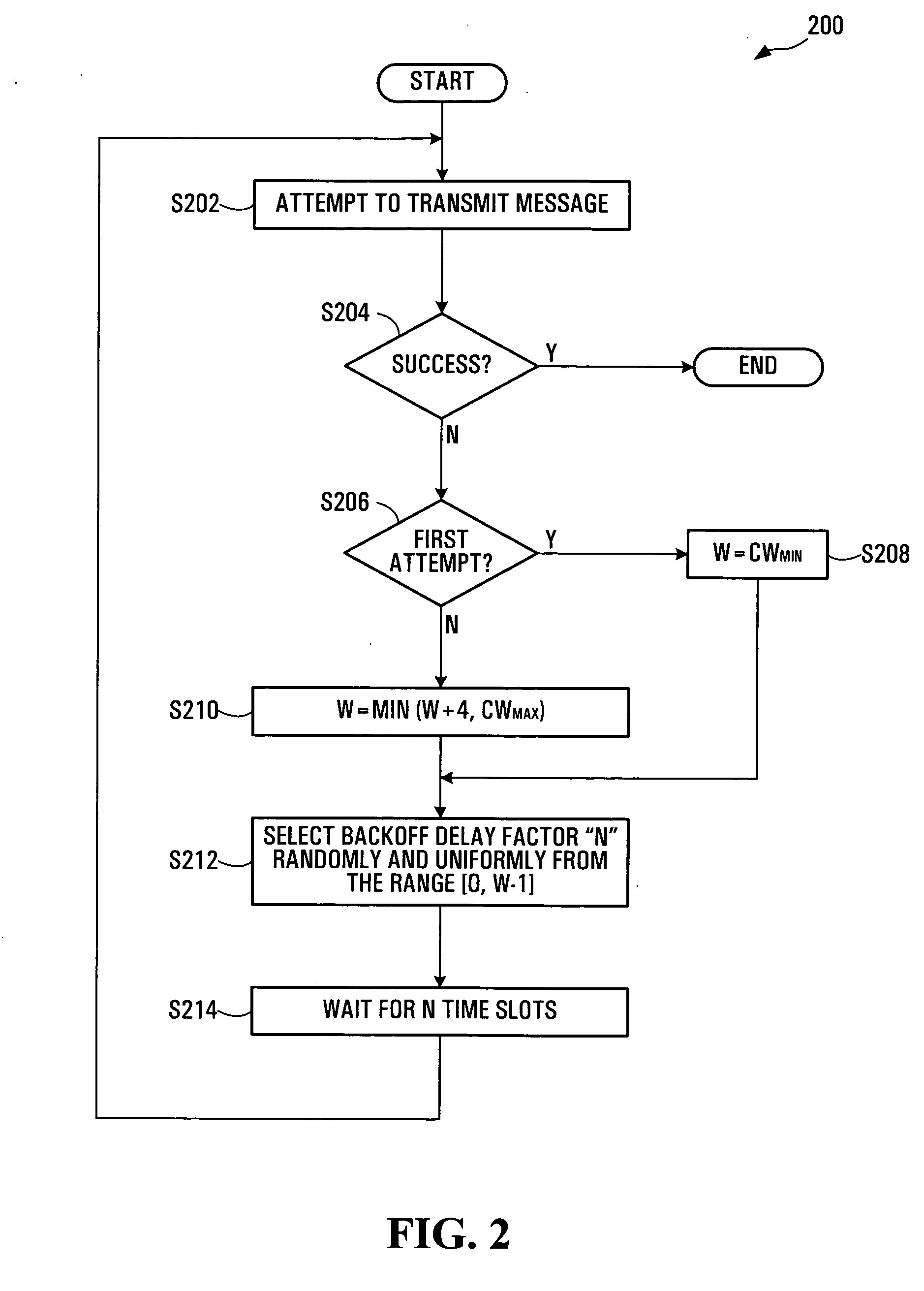
In a scheme for accessing a wireless network, a backoff delay time period representing a duration of time that is to elapse before a station is permitted to attempt a retransmission is selected from a group of delay periods. The group of delay periods grows at a rate that is less than exponentially (e.g. linearly) based on the number of attempted retransmissions. Selection of the backoff delay time period may entail random selection of an integer N from a contention window and multiplication of N by a slot time duration. The contention window may be a range of integers [0, W-1]. The contention window size W may be initialized to a predetermined minimum value upon a first attempted transmission and may be capped at a predetermined maximum value. Average backoff delay may be reduced in comparison to a binary exponential backoff approach.

Description

FIELD OF THE INVENTION [0001] The present invention relates to network access mechanisms, and more particularly to network access mechanisms used to access wireless local area networks. BACKGROUND OF THE INVENTION [0002] Wireless local area networks (LANs) have become ubiquitous in airports, coffee shops, enterprises and other locations in which wireless network access to data services is desirable. Many wireless LANs support the popular IEEE 802.11 standard for wireless LAN protocol, or one if its variants, such as 802.11a, 802.11b (“Wi Fi”), 802.11e, or 802.11g. The IEEE 802.11, 802.11a, 802.11b, 802.11e, and 802.11g standards are referred to herein as the “802.11 family of standards.”[0003] In each standard comprising the 802.11 family of standards, synchronous data transmissions are governed by the Distributed Coordination Function (DCF). The DCF governs shared access to the wireless medium based on the Carrier Sense Multiple Access / Collision Avoidance (CSMA / CA) protocol. The ba...

Claims


Application Information

Patent Timeline
IPC IPC(8): H04Q7/00H04L12/413H04W28/04H04W28/18H04W72/12H04W74/08
CPCH04L1/1887H04W28/04H04W74/085H04W72/12H04W28/18
Inventor BLOUIN, FRANCOIS
Owner NORTEL NETWORKS LTD
Learn More