Correction of NMR artifacts due to constant-velocity axial motion and spin-lattice relaxation

Active Publication Date: 2006-02-16
BAKER HUGHES INC
View PDF9 Cites 23 Cited by
  • Summary
  • Abstract
  • Description
  • Claims
  • Application Information

AI Technical Summary

Benefits of technology

[0021] The present invention is a method of processing and an apparatus used for processing Nuclear Magnetic Resonance (NMR) signals from an earth formation. The NMR tool is conveyed into a borehole in the earth formation and moved with an axial velocity in the borehole. Nuclear spins in the earth formations are polarized. An antenna on the NMR logging tool is pulsed with a pulse sequence to produce spin echo signals. The pulse sequence includes an excitation pulse and a plurality of refocusing pulses. The spin echo signals are correcte

Problems solved by technology

However, because of inhomogeneity in the static field due to the constraints on tool shape, imperfect instrumentation, or microscopic material heterogeneities, each nuclear spin precesses at a slightly different rate.
Tool motion can seriously affect the performance of NMR tools used in an MWD environment.
However, any axial or transverse (orthogonal to the tool axis) component of tool motion due to vibration will affect the NMR signal.
Rotation of the drillstring therefore causes (periodic) NMR signal losses during a spin echo train.
This discrepancy between ROP values is due to limited time resolution of the computer file as well as to flexibility of the drill string.
This requirement of having two different regions of examination complicates the hardware.
Another drawback (noted in Speier '874) to the above-described techniques is that the measurements must be separated in time and / or space.
The first is that T1 determination is time consuming.
A second drawback is that in the absence of an exact knowledge of the ratio of T1 / T2 , the method can only be used for quality control and not for determining both the T1 and T2 distributions.

Method used


Image

  • Correction of NMR artifacts due to constant-velocity axial motion and spin-lattice relaxation
  • Correction of NMR artifacts due to constant-velocity axial motion and spin-lattice relaxation
  • Correction of NMR artifacts due to constant-velocity axial motion and spin-lattice relaxation

Examples


Embodiment Construction

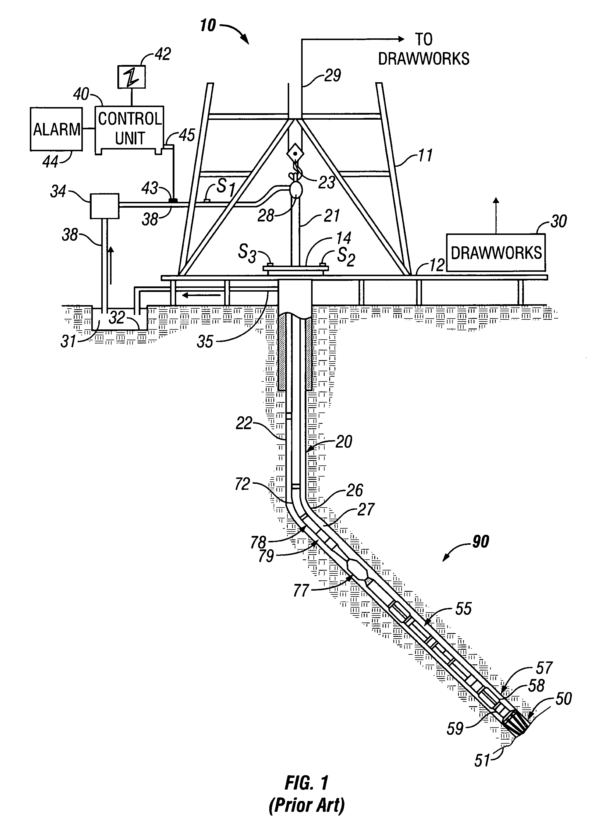
[0039]FIG. 1 shows a schematic diagram of a drilling system 10 with a drillstring 20 carrying a drilling assembly 90 (also referred to as the bottom hole assembly, or “BHA”) conveyed in a “wellbore” or “borehole”26 for drilling the wellbore. The drilling system 10 includes a conventional derrick 11 erected on a floor 12 which supports a rotary table 14 that is rotated by a prime mover such as an electric motor (not shown) at a desired rotational speed. The drillstring 20 includes a tubing such as a drill pipe 22 or a coiled-tubing extending downward from the surface into the borehole 26. The drillstring 20 is pushed into the wellbore 26 when a drill pipe 22 is used as the tubing. For coiled-tubing applications, a tubing injector, such as an injector (not shown), however, is used to move the tubing from a source thereof, such as a reel (not shown), to the wellbore 26. The drill bit 50 attached to the end of the drillstring breaks up the geological formations when it is rotated to dri...


PUM


Abstract

NMR spin echo signals are corrected for axial motion of the borehole logging tool. An additional correction may be applied to correct for incomplete polarization of nuclear spins due to an insufficient wait time between pulse sequences.

Description

BACKGROUND OF THE INVENTION [0001] 1. Field of the Invention [0002] The present invention relates generally to determining geological properties of subsurface formations using Nuclear Magnetic Resonance (“NMR”) methods for logging wellbores, particularly for correcting for the effects of tool motion and pulse sequence timing on NMR signals. [0003] 2. Description of the Related Art [0004] A variety of techniques are currently utilized in determining the presence and estimation of quantities of hydrocarbons (oil and gas) in earth formations. These methods are designed to determine formation parameters, including among other things, the resistivity, porosity and permeability of the rock formation surrounding the wellbore drilled for recovering the hydrocarbons. Typically, the tools designed to provide the desired information are used to log the wellbore. Much of the logging is done after the well bores have been drilled. More recently, wellbores have been logged while drilling, which i...

Claims


Application Information

Patent Timeline
IPC IPC(8): G01V3/00
CPCG01N24/081G01V3/32G01R33/56308G01R33/5617
Inventor BLANZ, MARTINTHERN, HOLGERKRUSPE, THOMAS
Owner BAKER HUGHES INC
Why Eureka
Try Eureka