
Synchronization system between aortic valve and cardiac assist device

a technology of aortic valve and aortic valve, which is applied in the field of synchronization system between aortic valve and cardiac assist device, can solve the problems of inability of the cardiac left ventricle to adequately perfuse the body with blood, further weakening the heart, and affecting the effect of cardiac left ventricle blood supply

Active Publication Date: 2006-02-09
KANTROWITZ ALLEN B +1
View PDF19 Cites 85 Cited by
  • Summary
  • Abstract
  • Description
  • Claims
  • Application Information

AI Technical Summary

Benefits of technology

[0009] A process for synchronizing a cardiac assist device in counter-pulsation with a left ventricle includes locating an acoustic or accelerometer sensor within a thoracic cavity of a mammal having the assist device coupled to the aorta of the mammal. Through the measurement of an acoustic or acceleration property of an aortic valve of the mammal, and the transmission of aortic valve closure measurement through a controller for the cardiac assist device, counter-pulsatile synchronization for the cardiac assist device is achieved.

Problems solved by technology

A major cause of death and disability is the failure of the cardiac left ventricle to adequately perfuse the body with blood.
Regardless of the cause, ineffectual ejection from the left ventricle further weakens the heart since the heart receives blood supply through coronary arteries during the resting phase.
Unfortunately, implanted pressure sensors tend to foul over time while noninvasive pressure sensors tend to shift position and detract from patient quality of life.
However, ferrofluid pumping to compress the heart remains an untested technology that is surgically intensive to implement.

Method used


Image

  • Synchronization system between aortic valve and cardiac assist device
  • Synchronization system between aortic valve and cardiac assist device

Examples


Embodiment Construction

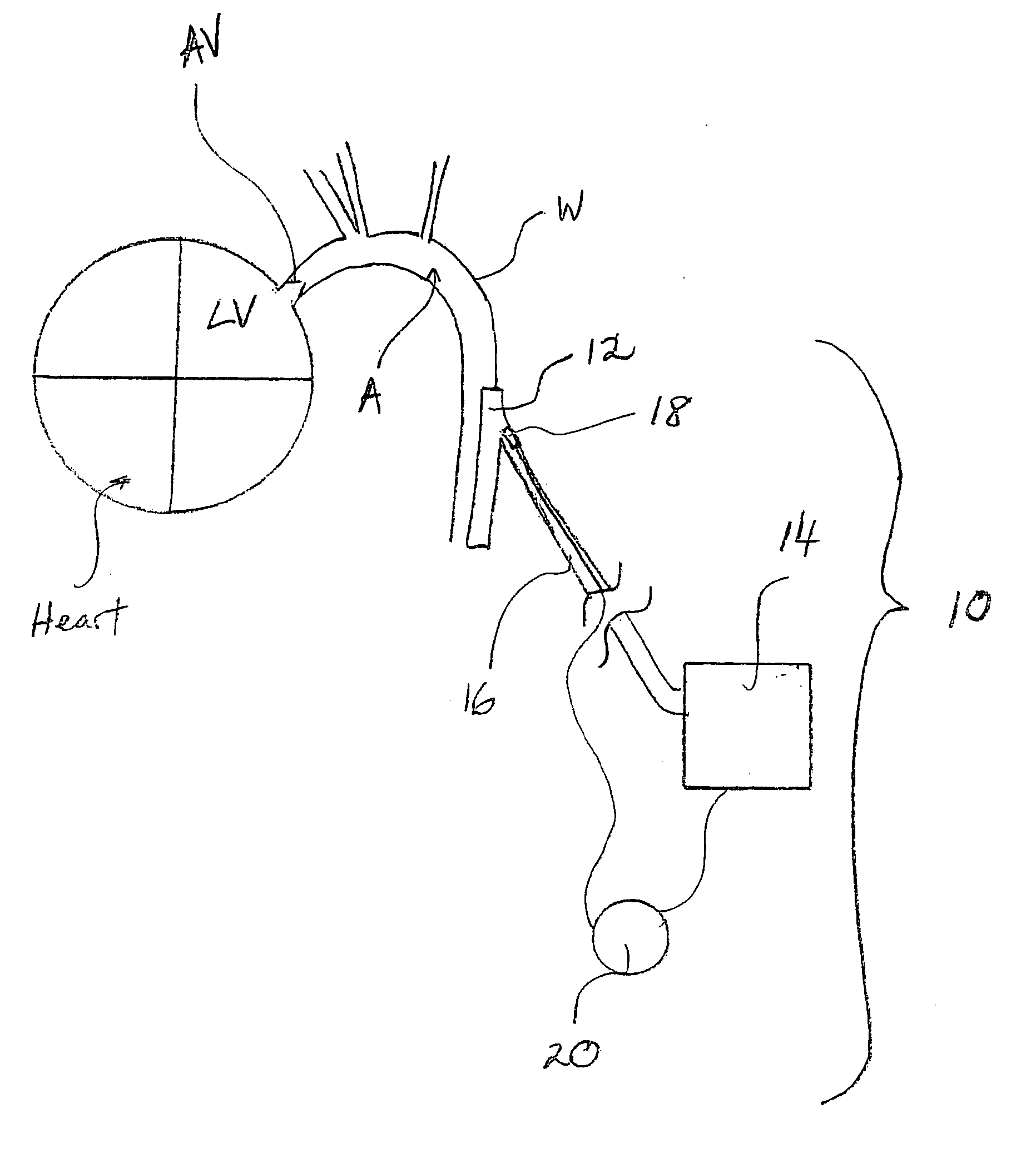
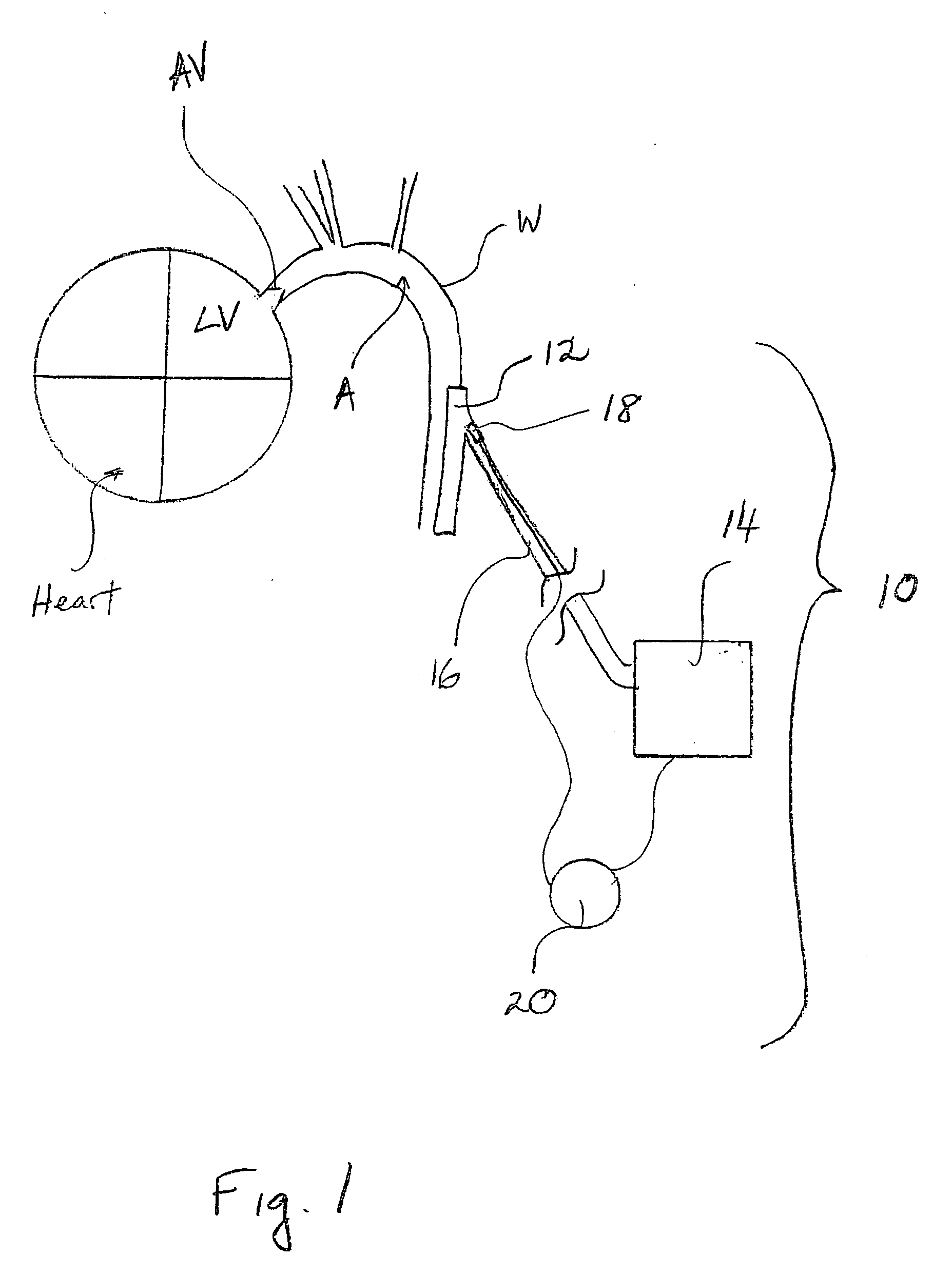
[0012] The present invention has utility as a synchronization system between closure of the aortic valve and a cardiac assist device. The present invention utilizes an acoustic or mechanical force associated with closure of the aortic valve as an input signal for the precise timing of counter-pulsation for an assist device. An inventive system is particularly well suited for endoscopic or minimally invasive insertion of a cardiac assist device.

[0013] According to the present invention, an acoustic sensor or mechanical force sensor is placed in proximity to the aortic valve in order to accurately sense aortic valve closure with the use of this signal as a timing input to a cardiac assist device such as an LVAD. The acoustic sensor preferably takes the form of a microphone, ultrasonic transducer or Doppler sensor. More preferably, the acoustic sensor is dimensioned so as to be surgically implantable. Preferably, a mechanical sensor according to the present invention is an acceleromet...


PUM


Abstract

A cardiac assist device synchronization system includes a cardiac assist device and an acoustic or accelerometer sensor that provides a signal input to the cardiac assist device indicative of aortic valve closure. The cardiac assist device is coupled to a mammalian aorta and includes an inflatable chamber and a fluid pump. A fluid conduit is in communication between the chamber and the pump to provide for selective inflation of the chamber. A pump controller triggers the pump in counter-pulsation to a mammalian heart upstream from the aorta. A process for synchronizing a cardiac assist device in counter-pulsation with a left ventricle includes locating an acoustic or accelerometer sensor within a thoracic cavity of a mammal having the assist device coupled to the aorta of the mammal. Through the measurement of an acoustic or acceleration property of an aortic valve of the mammal, and the transmission of aortic valve closure measurement through a controller for the cardiac assist device, counter-pulsatile synchronization for the cardiac assist device is achieved.

Description

RELATED APPLICATION [0001] This application claims priority of U.S. Provisional Patent Application Ser. No. 60 / 586,537 filed Jul. 9, 2004, which is incorporated herein by reference.FIELD OF THE INVENTION [0002] The present invention in general relates to a cardiac assist device and more specifically to controlled pulsation of such an assist device in cooperation with a subject heart. BACKGROUND OF THE INVENTION [0003] A major cause of death and disability is the failure of the cardiac left ventricle to adequately perfuse the body with blood. While numerous disease conditions cause left ventricular failure, coronary artery disease is perhaps the most common. Regardless of the cause, ineffectual ejection from the left ventricle further weakens the heart since the heart receives blood supply through coronary arteries during the resting phase. As the heart muscle loses the ability to pump blood, both systolic and diastolic blood pressures are reduced with a reduced diastolic pressure. T...

Claims


Application Information

Patent Timeline
Patent Type & Authority Applications(United States)
IPC IPC(8): A61N1/362A61M60/178A61M60/268A61M60/427A61M60/515A61M60/538A61M60/857
CPCA61M1/106A61M1/122A61M1/1072A61M2205/33A61M2205/3303A61M60/268A61M60/148A61M60/857A61M60/427A61M60/178A61M60/538A61M60/515
Inventor KANTROWITZ, ALLEN B.KANTROWITZ, ADRIAN
Owner KANTROWITZ ALLEN B
Learn More