Ejector Nozzle

Inactive Publication Date: 2006-02-09
GRATTEAU MR JACK EDWARD
View PDF13 Cites 37 Cited by
  • Summary
  • Abstract
  • Description
  • Claims
  • Application Information

AI Technical Summary

Benefits of technology

[0007] The object of this design is to enable the construction of an efficient ejector using stock available shapes and simple fabrication methods. The resulting component can be made out of a wide variety of materials and formed as needed to the application.
[0011] The exit ends of the tubes that surround the main nozzle can be shaped to form a fan discharge pattern radial to the core flow path. The tube end could be squeezed to form a more narrow flow passage, or cut at an angle away from the flow path. With the tubes exit ends cut at angle, the noise of the ejector can be reduced over that of a simple blunt cut orifice.

Problems solved by technology

The operating environment places restrictions on what materials and fabrication methods may be applied.
In jet aircraft, these structures are subject to high pressures and temperatures.
For hydraulic applications in a corrosive or abrasive regimen, folded structures like that that used in gas turbines are limited by materials compatibility that can be so formed.
For lesser applications in small gas turbines, the expense of the nozzle and related components impede the broader adoption of ejector technologies.

Method used


Image

  • Ejector Nozzle
  • Ejector Nozzle
  • Ejector Nozzle

Examples


Embodiment Construction

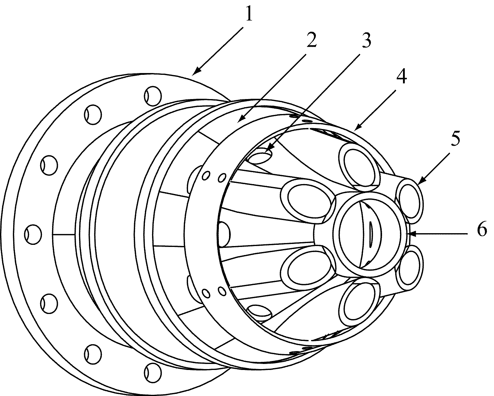
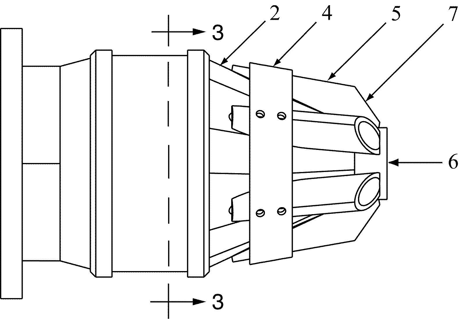
[0017] The nozzle assembly depicted in FIG. 1 is an off-axis view from the perspective of the ejector jet exit. The inlet flange 1 is intended to illustrate any generic means to couple the jet nozzle to the source of supply. The convergent cone 2 then conveys the motive fluid to the primary central jet, which in this example is terminated by a short tube 6.

[0018] Around the cone 2 are disposed a plurality of tubes 5 that intersect with the cone 2 and converge with the primary jet 6. The tubes 5 are arranged around the primary jet 6 such that there is space between each tube 5 exit. The inlet of the tubes 5 are cut at an acute angle at the plane of the surface of cone 2 to affix the tubes 5 to the cone 2 as described.

[0019] Proximal to the inlet end of the tube 5 bundle a collar 4 is disposed at that circumference. Underneath the collar 4, passage holes 3 penetrate the convergent nozzle 2. The passage holes 3 could be any number or shape as needed. The collar 4 could be circular or...


PUM


Abstract

A multi-lobed ejector nozzle of economical construction and simple form is described. The lobes are formed by a plurality of short tubes that intersect with a central jet. Coanda jets upstream of the ejector formed by a collar and multiple apertures further assist the induction of an external flow to the primary ejector. Shaping of the tube nozzles aid in forming the ejector lobes. The nozzle geometry and the Coanda ring contribute to a reduction in the noise of the ejector assembly.

Description

BACKGROUND OF INVENTION [0001] An ejector nozzle is a device that couples the jet flow of a primary fluid stream with a surrounding fluid, inducing a flow in that fluid. These fluids may be liquids, gas, slurries, or mixtures of both. Ejector nozzles vary in complexity from a simple pipe, to complex geometries as may be useful for noise or efficiency. [0002] Common to most nozzles is a convergent section of the primary flow about which the secondary flow is drawn into by the suction effect of the core fluid stream. It has been found that the efficiency of an ejector nozzle can be improved by structuring the flow into multiple lobes about a common jet. The multiple lobes increase the surface area of the jet stream, while the convergent section maintains a high velocity in the jet. [0003] Air breathing jets, hydraulic jet pumps, and mixers are common applications that employ ejector type nozzles. The operating environment places restrictions on what materials and fabrication methods m...

Claims


Application Information

Patent Timeline
IPC IPC(8): B05B1/28B05B1/14B05B7/08A62C2/08
CPCF02K1/40
Inventor GRATTEAU, JACK EDWARD
Owner GRATTEAU MR JACK EDWARD
Why Eureka
Try Eureka