Microfluidic devices and methods with integrated electrical contact

Inactive Publication Date: 2006-02-02
NORVIEL VERN
View PDF99 Cites 47 Cited by
  • Summary
  • Abstract
  • Description
  • Claims
  • Application Information

AI Technical Summary

Benefits of technology

[0008] In various embodiments, microfluidic devices include improved mechanisms for causing substances to pass from the microfluidic device to the MS via electrospray ionization (ESI). Generally, microfluidic devices include a substrate comprising at least one microchannel, a cover arranged on a surface of the substrate, at least one outlet in fluid communication with the microchannel for allowing egress of substances, and at least one tip surface extending the cover beyond the outlet. Devices also typically include one or more electrical potential sources, such as electrodes, to provide ESI. Improved design configurations and the like provide for enhanced ESI from a microfluidic device that may also provide for separation and / or other manipulation of substances.
[0010] In some embodiments, the microchannel is enclosed between the substrate and the cover. Also in some embodiments, the at least one microchannel comprises at least two intersecting microchannels. In these or other embodiments, the at least one microchannel may include a first microchannel in fluid communication with a first outlet and having first cross sectional dimensions and second, wider cross sectional dimensions, and at least a second microchannel in fluid communication with a second outlet disposed at the tip surface. Optionally, the second microchannel may include at least one substance, such as but not limited to a cross-linked polyacrylamide, an agarose gel, a linear polyacrylamide, a cellulose polymer, polyethylene oxide, polyvinylpyrrolidone and other hydrophilic polymer solutions, for preventing substances exiting the first outlet from entering the second outlet. Alternatively, the second microchannel may have negatively charged walls for directing a buffer through the second microchannel to prevent substances exiting the first outlet from entering the second outlet. In another embodiment, the first microchannel may have positively charged walls, and the second microchannel may have walls with essentially no charge or a very low charge, for preventing substances from entering the second outlet.
[0023] In other embodiments, the electrical potential source comprises at least one electrode on the microfluidic device. For example, the at least one electrode may comprise a strip of material, such as a metal film or conductive ink, coupled with the cover so as to be disposed across the outlet. Such an electrode may be embedded in the cover, coupled with the cover via adhesive, or coupled with the cover via any other suitable means. In some embodiments, the at least one electrode provides potential for effecting at least one of electrophoretic separation of the substances and electrospray ionization. In other embodiments, the at least one electrode provides potential for effecting at least one of electrokinetic movement of the substances in the microchannel and electrospray ionization. The at least one electrode may comprise any suitable material or materials, such as but not limited to copper, nickel, conductive ink, silver, silver / silver chloride, gold, platinum, palladium, iridium, aluminum, titanium, tantalum, niobium, carbon, doped silicon, indium tin oxide, other conductive oxides, polyanaline, sexithiophene, polypyrrole, polythiophene, polyethylene dioxythiophene, carbon black, carbon fibers, conductive fibers, and / or other conductive polymers and conjugated polymers. In some embodiments, the at least one electrode provides the electrical potential without producing a significant quantity of bubbles in the substances.

Problems solved by technology

One of the challenges in developing microfluidic devices has been to combine the ability of a device to separate, mix or otherwise manipulate sample substances with its ability to provide those substances to a MS device via ESI.
One problem sometimes encountered in currently available microfluidic ESI devices is the challenge of applying a potential to substances in the device with a stable ionization current while minimizing dead volume and minimizing or preventing the production of bubbles in the channels or in the droplet at the microchannel outlet.
The conductive coating, however, often erodes or is otherwise not reproducible.
Furthermore, bubbles are often generated in currently available devices during water electrolysis and / or redox reactions of analytes.
Such bubbles adversely affect the ability of an ESI device to provide substances to a mass spectrometer in the form of a spray having a desired shape.
In particular, the presence of one or more bubbles in the microfluidic channel of a microfluidic device can interrupt both the flow and the electrical current needed to sustain electrospray ionization, thus destabilizing the electrospray and disabling the device.
Minimizing dead volume at the tip of the microfluidic device, as mentioned above, enhances sensitivity and separation performance of a microfluidic device but has proven difficult.
Another difficulty in developing microfluidic devices with ESI tips is to minimize or eliminate electrical breakdown between the ESI tip and the MS counter electrode.

Method used


Image

  • Microfluidic devices and methods with integrated electrical contact
  • Microfluidic devices and methods with integrated electrical contact
  • Microfluidic devices and methods with integrated electrical contact

Examples


Embodiment Construction

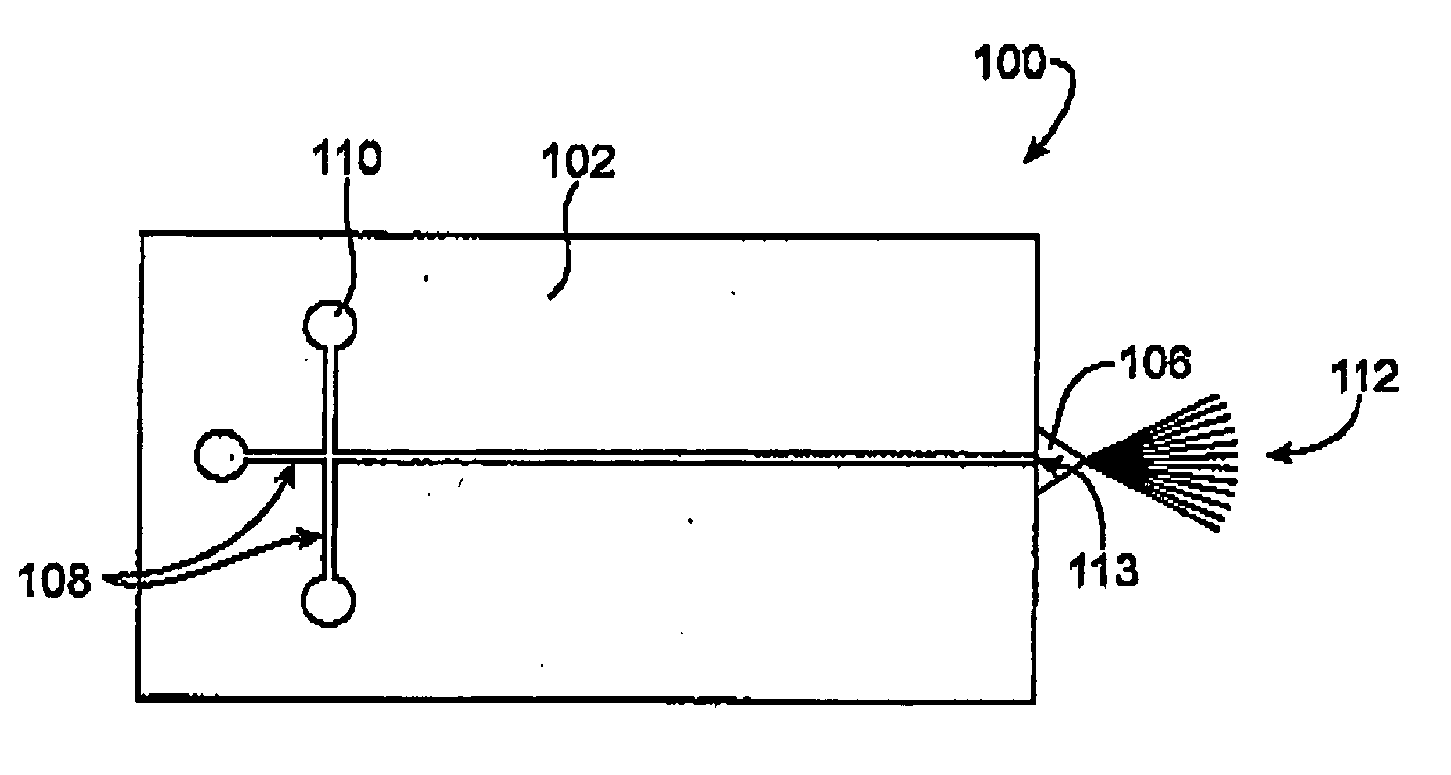
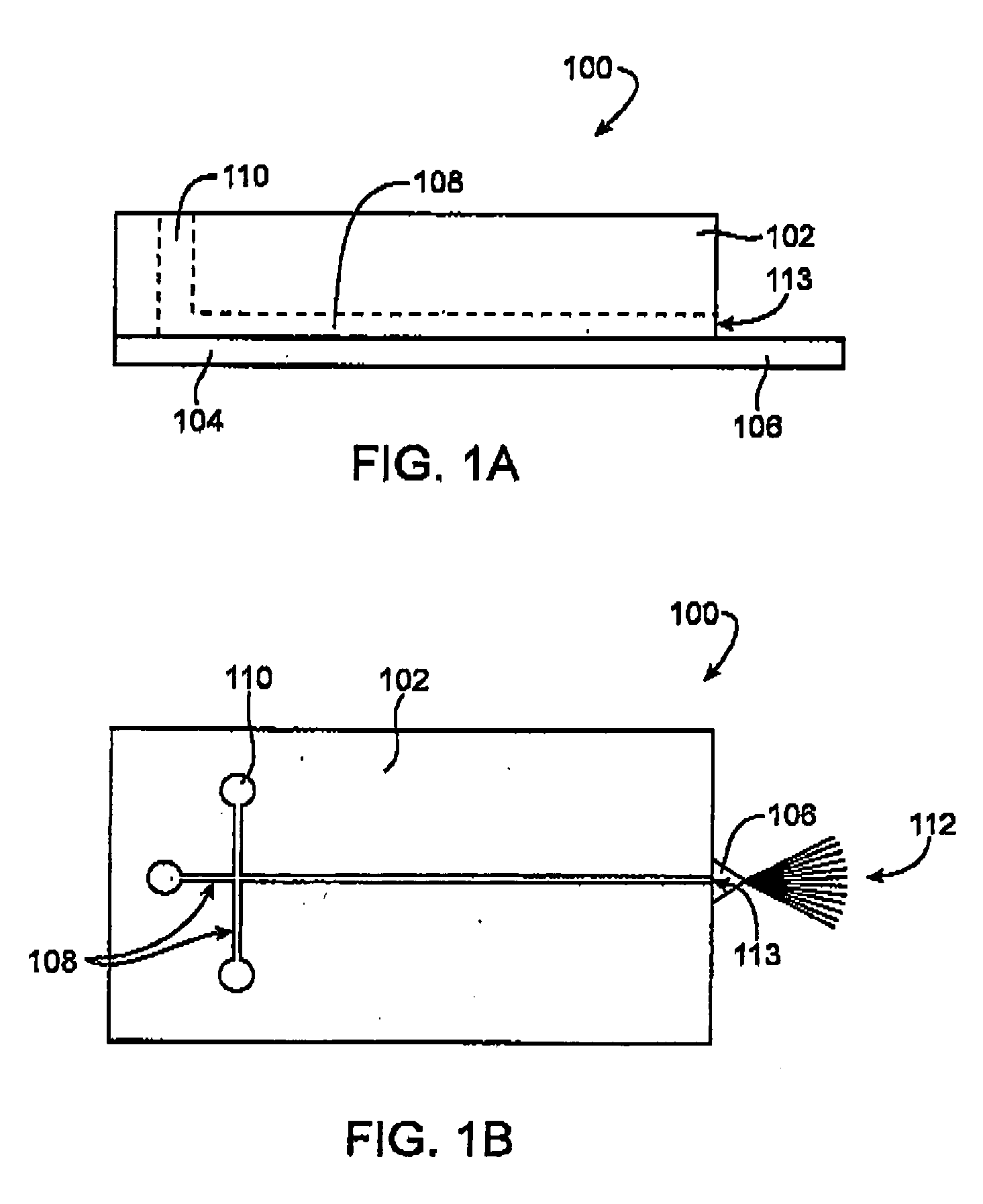
[0039] Improved microfluidic devices and methods for making and using such devices provide one or more substances to a mass spectrometer (MS) for analysis. The microfluidic devices generally include a substrate and a cover (or a substrate having first and second surfaces or the like), at least one microchannel formed by the surfaces, an outlet at an edge of the surfaces, and at least one electrical potential source. In various embodiments, different features of the substrate, cover, outlet and / or electrical potential source are configured to enhance electrospray ionization (ESI) of substances from a microfluidic device to a MS device for analysis.

[0040] Referring now to FIGS. 1A and 1B, schematic illustrations of a side view and a top view, respectively, of a microfluidic device 100 comprising a substrate 102 and a cover 104 are shown. (The device 100 is not drawn to scale.) The substrate 102 includes one or more wells 10, into which substance(s) may be deposited, and one or more m...


PUM


Abstract

Microfluidic devices provide substances to a mass spectrometer. The microfluidic devices include a substrate having at least one microchannel, a cover arranged on a surface of the microchannel, and at least one electrical potential source. Some embodiments include a microchannel widened at an outlet. Other embodiments position the electrical potential source along a surface of the cover. Still other embodiments include a well in which an electrode and a membrane are disposed. The various embodiments provide stable electrospray ionization of substances from a microfluidic device to a mass spectrometer.

Description

FIELD OF THE INVENTION [0001] The present invention relates generally to interfaces between microfluidic devices and mass spectrometers. More specifically, the invention relates to improved microfluidic devices for providing electrospray ionization of substances to a mass spectrometer. BACKGROUND OF THE INVENTION [0002] The use of microfluidic devices such as microfluidic chips is becoming increasingly common for such applications as analytical chemistry research, medical diagnostics and the like. Microfluidic devices may be used for separation and analysis of sample sizes as small as a few nanoliters or less and are thus generally quite promising for applications such as proteomics and genomics. One way to analyze substances using a microfluidic device is to mix and / or separate substances on the microfluidic device and then pass the substances from the device to a mass spectrometer (MS). Such a technique often uses electrospray ionization (ESI) to pass the substances from the micro...

Claims


Application Information

Patent Timeline
IPC IPC(8): H01J49/00
CPCB01L3/0268H01J49/165H01J49/0018B01L3/5027
Inventor BOUSSE, LUCZHAO, MINGQINI, JING
Owner NORVIEL VERN
Why Eureka
Try Eureka