
Reconfigurable operation apparatus

a dynamic reconfigurable and operation apparatus technology, applied in the direction of instruments, computations using denominational number representations, and architectures with multiple processing units, can solve the problems of high probability of data transfer delay, pre-selecting a series of alu modules suitable for arbitrary algorithms, and difficult to use disparate operation elements for pe arrays, etc., to achieve speedy reconfiguration and high processing efficiency

Inactive Publication Date: 2006-01-12
FUJITSU LTD
View PDF8 Cites 42 Cited by
  • Summary
  • Abstract
  • Description
  • Claims
  • Application Information

AI Technical Summary

Benefits of technology

[0021] Another purpose of the present invention is to provide a reconfigurable operation apparatus gaining uniform and good process efficiency independent of a process element allocation or process control architecture.
[0022] Yet another purpose of the present invention is to provide an operation apparatus capable of including optional disparate processor elements therein and of speedily reconfigurable thereof.
[0025] A reconfigurable operation apparatus according to the present invention provides a uniform, high processing efficiency independent of an allocation of processor elements or of control architecture.
[0026] Also according to the present invention, it is possible to include diverse processor elements and accomplish a speedy reconfiguration.

Problems solved by technology

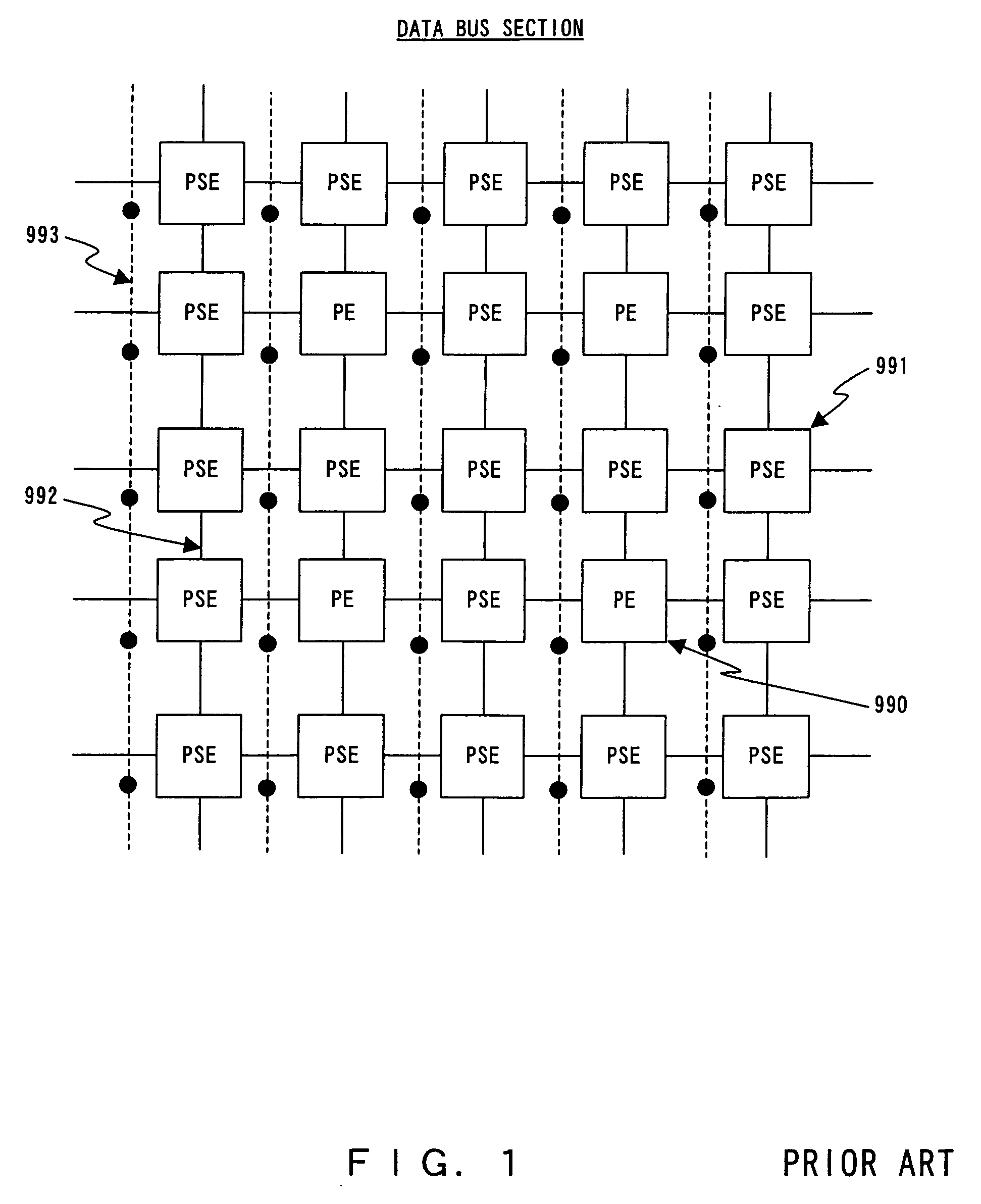
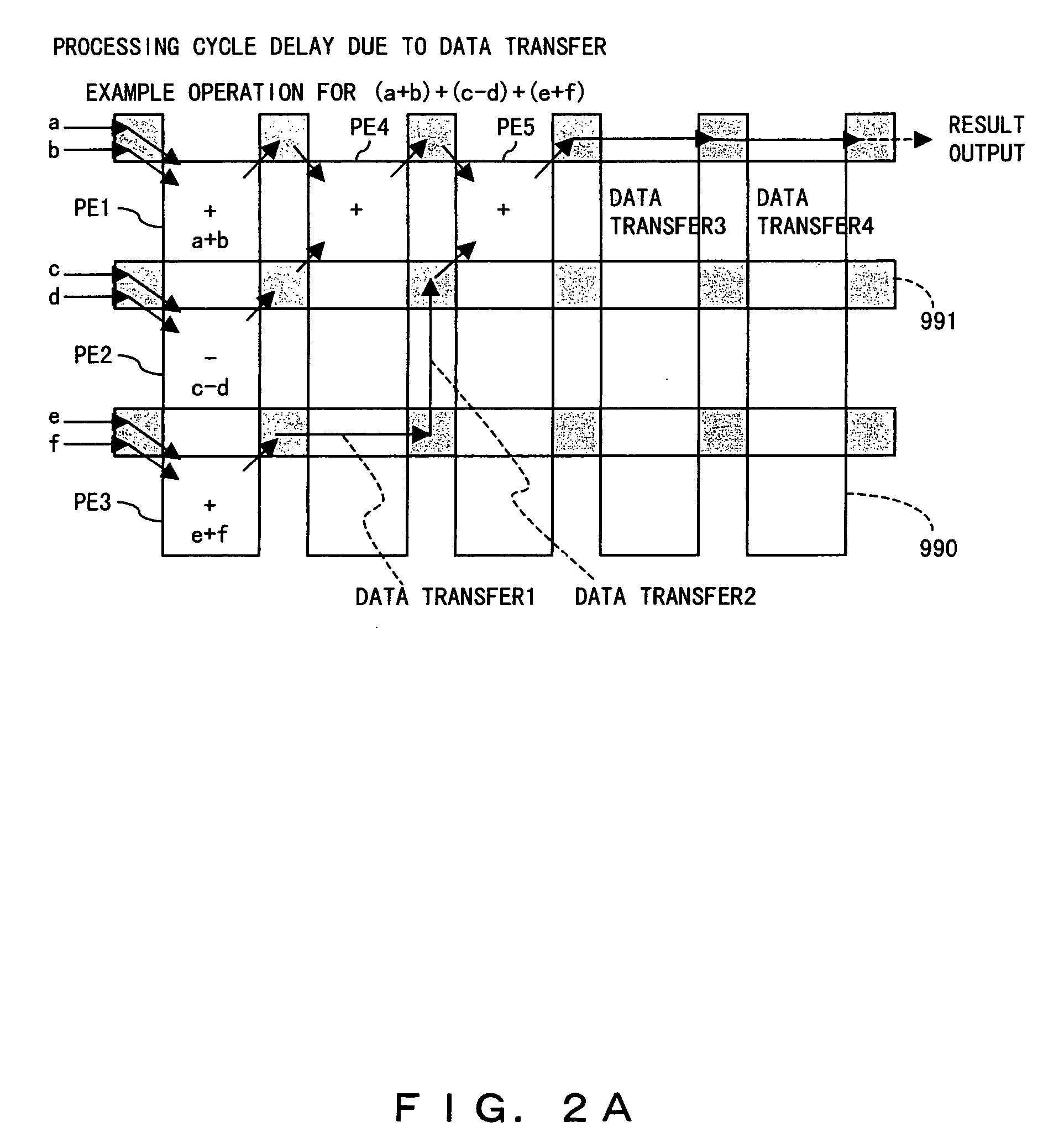
That is, as observed in the Japanese patent laid-open application publication No. 2001 312481, the comprisal in which not only the processor elements but also switch elements used for data transfers between the processor elements can cause a high probability of a delayed processing associated with data transfers.
Therefore, if a PE array is tried to be comprised by disparate ALU modules in a type of operation apparatus transferring data between adjacent switch elements, efficiencies of the processing will vary a great deal depending on the algorithm because it is impossible to pre-select a series of ALU modules suitable for arbitrary algorithms during the production stages according to the conventional techniques.
As such, it is difficult to use disparate operation elements for the PE array in constituting a PE array reconfigurable operation apparatus transferring data between operation elements by way of the two-dimensional array of switch elements.
While there is one feedback cycle for the example above, as the number of cycles prior to a loop-back increases, the distance for returning in a feedback becomes longer, and therefore a loss in the process efficiency will become worse accordingly.
As described, also the process control architecture closely affects the process efficiency of a PE array reconfigurable operation apparatus transferring data between processor elements by way of the two-dimensional array of switch elements, and therefore a further loss in the process efficiency can incur, depending on a loop processing.
There is a problem associated with time being taken in a reconfiguration of the ALU modules, which occurs in changing the processing content, at the detection of a conditional branching, et cetera.
Therefore an accumulation of such switching time with the number of reconfiguration occurrence can possibly cause overall performance degradation.
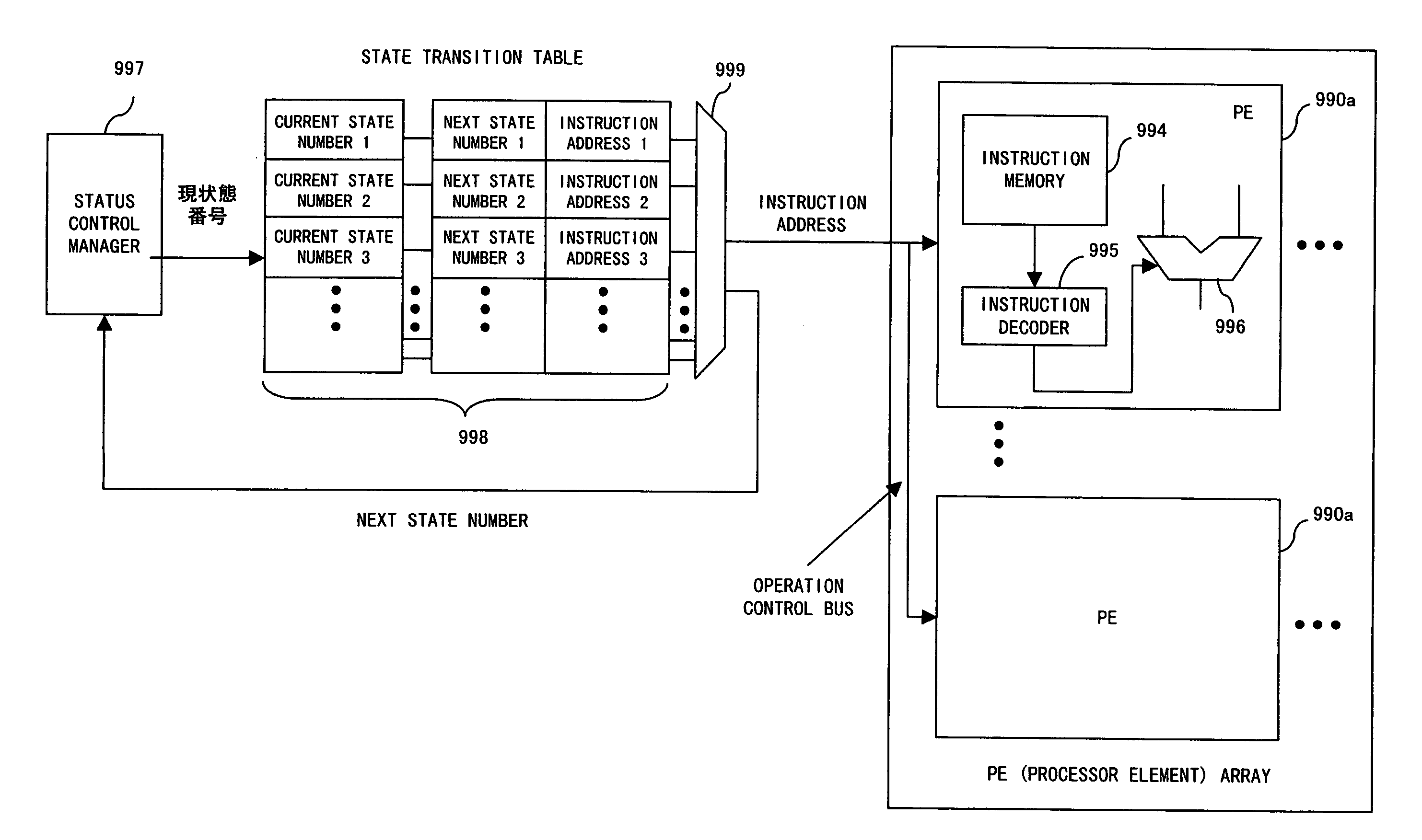
Therefore, a delay between searching in the state transition table and the actual arithmetic and logical operation becomes problematic.
The state transition table is a memory whose size becomes larger with the number of entries, which in turn causes the problem of the area size becoming larger.

Method used


Image

  • Reconfigurable operation apparatus
  • Reconfigurable operation apparatus
  • Reconfigurable operation apparatus

Examples


embodiments

[0090]FIG. 7 is a summary conceptual block diagram of a reconfigurable operation apparatus according to the present invention.

[0091] In FIG. 7, the reconfigurable operation apparatus 1 is equipped with a processor element network 10 in which diverse processor elements are interconnected by an inter-processor element network 40. The diverse processor elements interconnected by the inter-processor element network 40 include a plurality (four in the example shown in FIG. 7) of ALU modules 20, a data memory 240, a data input port 220, a data output port 230, various processor elements 250, et cetera, for example. Not only the ALU module 20 but also the other diverse processor elements can be set up so as to perform a function related to a configuration data supplied from the outside. Furthermore, the inter-processor element network 40 also enables data transfers among the diverse processor elements interconnected by the inter-processor element network 40 corresponding to a configuratio...


PUM


Abstract

A reconfigurable operation apparatus consists of a plurality of operation units capable of reconfiguring themselves by using a piece of given first configuration data and of operating simultaneously with one another; RAMs; diverse processor elements required for constituting an operation apparatus; an inter-resource network interconnecting the operation units, the RAMs and the diverse processor elements, performing data transfers between resources connected thereto in a uniform transfer time independent of positions and kinds of the resources, and being reconfigurable by using a given second configuration data; and a configuration memory storing the first and the second configuration data. Configuration data is loaded from an external storage apparatus onto the configuration memory, and the first and the second configuration data are supplied to the reconfigurable processor resources in appropriate sequence and timing based on data available from a plurality of operation units.

Description

CROSS-REFERENCE TO RELATED APPLICATIONS [0001] This application is based upon and claims the benefit of priority from the prior Japanese Patent Application No. 2004-205332 filed on Jul. 12, 2004, the entire contents of which are incorporated herein by reference. BACKGROUND OF THE INVENTION [0002] 1. Field of the Invention [0003] The present invention relates to a dynamically reconfigurable operation apparatus capable of operating diverse processing by dynamically reconfiguring itself. [0004] 2. Description of the Related Art [0005] A method for making a reconfigurable operation apparatus operate a plurality of tasks has conventionally been classified into two types: one, the space parallelism in which the circuit thereof is divided spatially and a task is allocated to each circuit; and two, the time parallelism in which the configuration is switched to a time sharing system for operating different tasks. The present invention relates to an operation apparatus, belonging to the latte...

Claims


Application Information

Patent Timeline
IPC IPC(8): G06F15/00
CPCG06F15/8007G06F7/38
Inventor SAITO, MIYOSHIFUJISAWA, HISANORIYOSHIZAWA, HIDEKITANIZAWA, TETSUKASAMA, ICHIROKAWANO, TETSUOIMAFUKU, KAZUAKIFURUKAWA, HIROSHIURIU, SHIROWAKAYOSHI, MITSUHARU
Owner FUJITSU LTD
Learn More