Voltage reference circuit using PTAT voltage
- Summary
- Abstract
- Description
- Claims
- Application Information
AI Technical Summary
Benefits of technology
Problems solved by technology
Method used
Image
Examples
Embodiment Construction
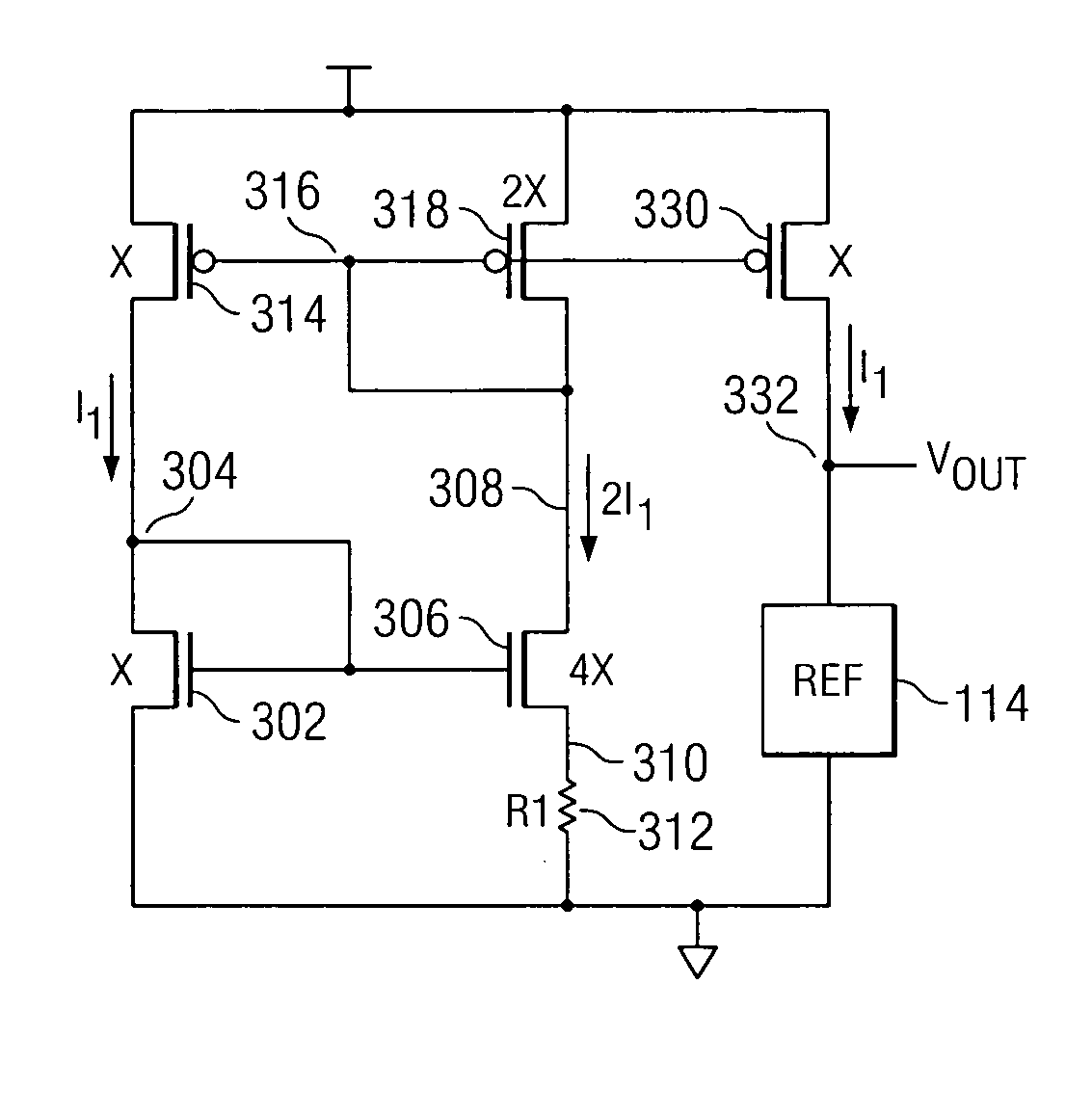
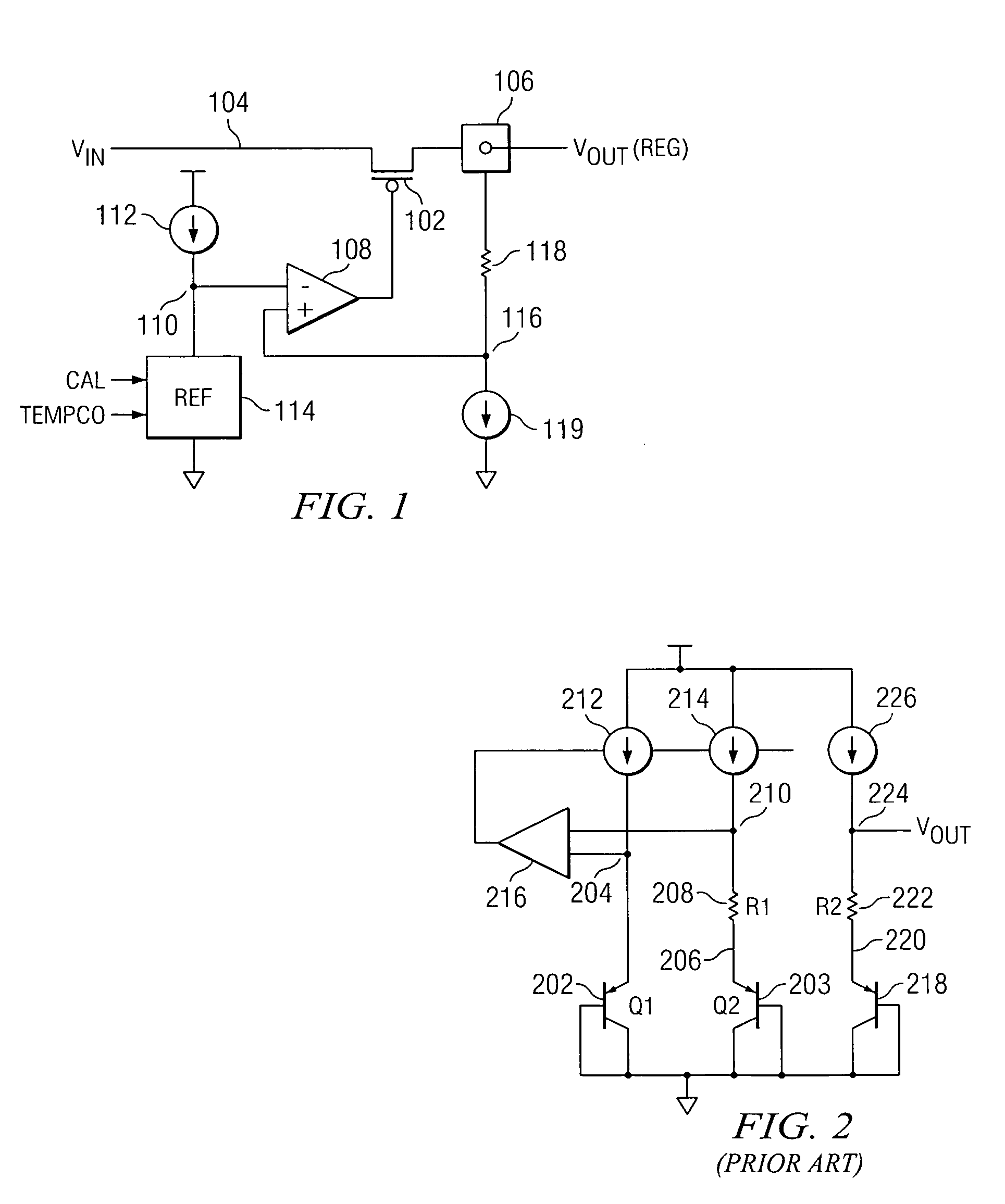
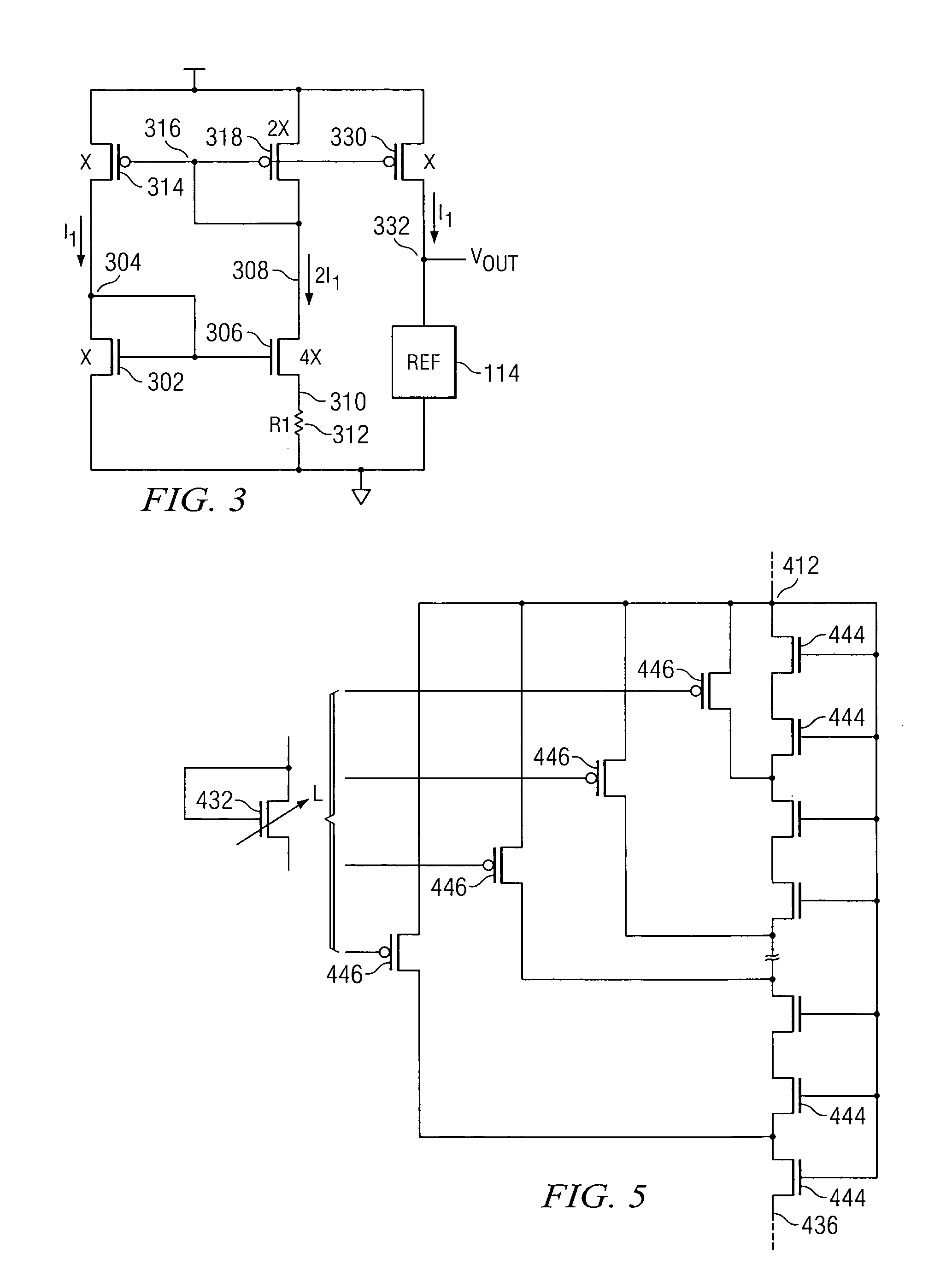
[0012] Referring now to FIG. 1, there is illustrated a diagram for a voltage regulator. The voltage regulator basically is comprised of a p-channel pass transistor 102 having the source / drain thereof connected between an input voltage on node 104 and a regulated output voltage on output pad 106. The output regulated voltage on the output pad 106 drives the on-chip circuitry associated therewith (not shown). This is the regulated voltage output. The gate of the transistor 102 is driven by an amplifier 108 that provides the regulating voltage. The negative input of amplifier 108 is connected to a node 110. Node 110 has a current driven thereto by a current source 112 connected between the supply voltage and node 110 for driving a reference load device 114. The reference load device 114 will be described in detail herein below. The current source 112 provides a current that is a Proportional To Absolute Temperature (PTAT) current. This current has a Positive Temperature Coefficient (PT...
PUM
 Abstract
Description
Claims
Application Information
 - R&D
- Intellectual Property
- Life Sciences
- Materials
- Tech Scout
- Unparalleled Data Quality
- Higher Quality Content
- 60% Fewer Hallucinations
Browse by: Latest US Patents, China's latest patents, Technical Efficacy Thesaurus, Application Domain, Technology Topic, Popular Technical Reports.
© 2025 PatSnap. All rights reserved.Legal|Privacy policy|Modern Slavery Act Transparency Statement|Sitemap|About US| Contact US: help@patsnap.com


