
Ink jet nozzle geometry selection by laser ablation of thin walls

a technology of laser ablation and nozzle geometry, which is applied in the direction of printing, etc., can solve the problems of asymmetric nozzles, serious problems, and limitations of processing, and achieve the effect of facilitating the exit of print drops during printing

Inactive Publication Date: 2005-12-29
XEROX CORP
View PDF5 Cites 19 Cited by
  • Summary
  • Abstract
  • Description
  • Claims
  • Application Information

AI Technical Summary

Benefits of technology

[0007] In view of the above-identified problems and limitations of the prior art, the present invention provides a method of fabricating ink jet printheads including: an array of lithographically fabricating channels having side walls formed from a photopolymer in which the end of the channels are closed by a thin layer of photopolymer; t

Problems solved by technology

Irregular or otherwise asymmetric nozzles can be a serious problem for any jetting device.
These irregularities can be the result of limitations to the processing.
Further, the dicing process itself can introduce eccentricities around the nozzle in the form of burrs, chips, and other undesirable features of the dicing process.
Because they may affect geometries, the aforementioned remnants of the fabrication and dicing processes can often cause exiting ink drops to veer off their intended paths resulting in “directionality” problems that can affect print quality.
Often, however, remnants that may affect geometry and directionality still remain after cleaning.
Also, the application of a hydrophobic coating can contaminate the interior fluidic pathways, leading to air entrapment or “depriming” of the channel.
There are other problems associated with prior art ink jet printhead fabrication techniques which rely on dicing to create the nozzle openings.

Method used


Image

  • Ink jet nozzle geometry selection by laser ablation of thin walls
  • Ink jet nozzle geometry selection by laser ablation of thin walls
  • Ink jet nozzle geometry selection by laser ablation of thin walls

Examples


Embodiment Construction

[0014] The reader is again referred to the Markham patent for general details about the fabrication of ink jet printheads, and the general operation of ink jet printheads, as said reference is also incorporated by reference. Of note in the Markham patent is the use of laser ablation to construct a printhead filter, as the present invention also employs laser ablation, but for an entirely different purpose-to construct nozzle exit holes.

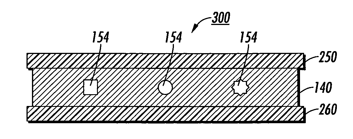
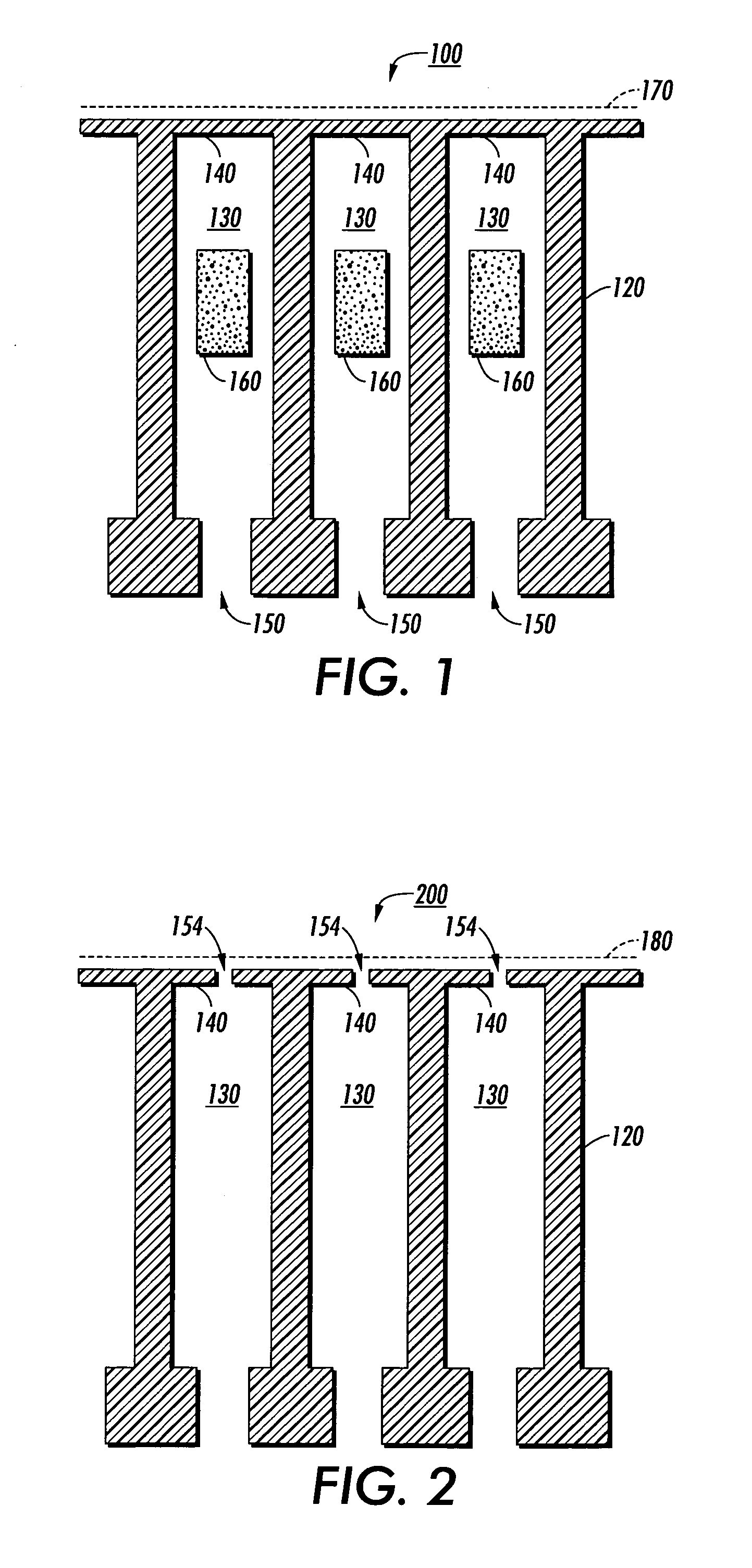
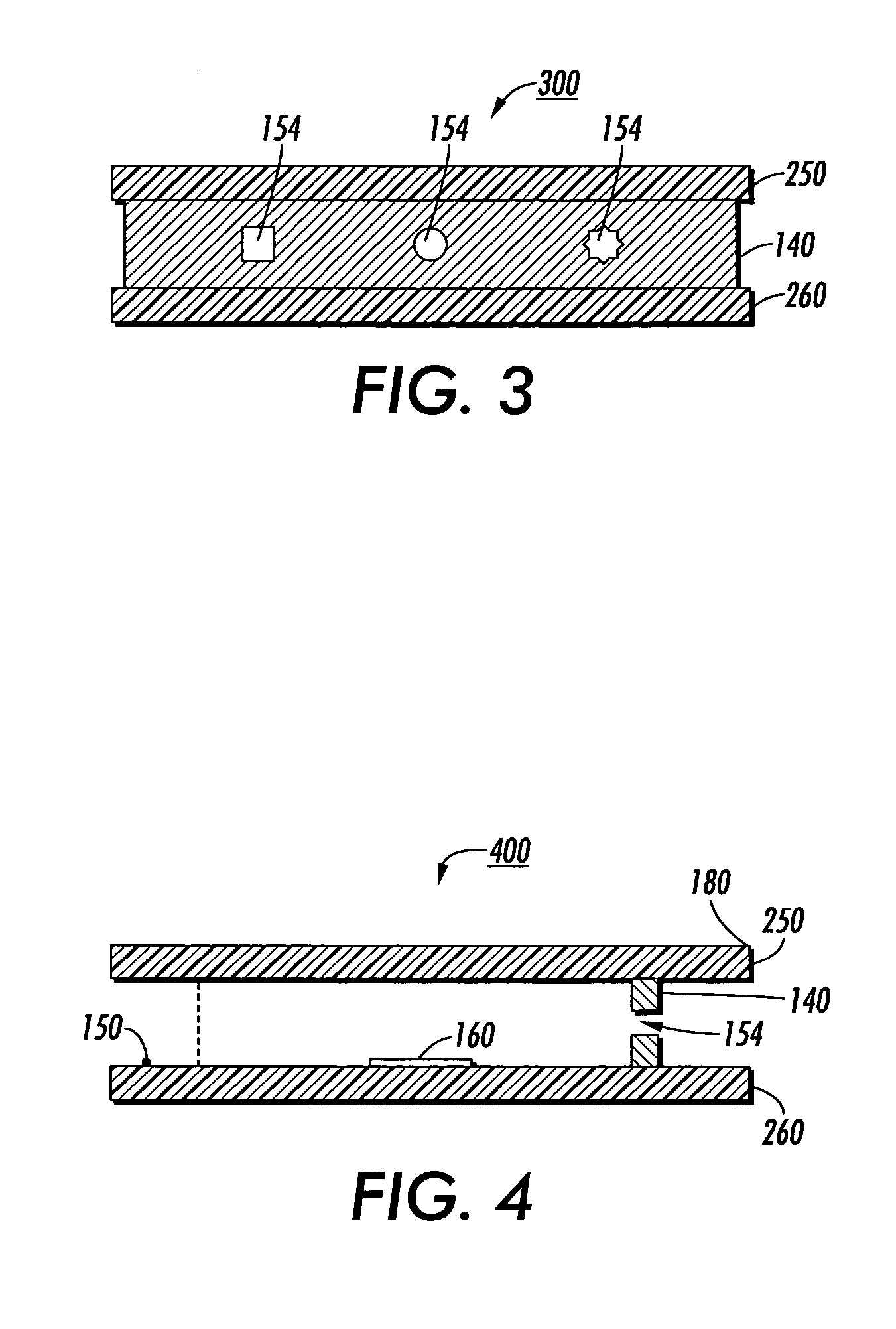
[0015]FIG. 1 illustrates the top view of the preferred embodiment for a partially fabricated thermal printhead 100. The printhead 100 is of the “side-shooting” type, although the present invention can be applied to other printhead types. In this figure, the following steps have already occurred. Walls such as those numbered 120 have been lithographically formed to create channels 130 having thin walls 140 blocking the one end of the channels and an opening to the manifold 150 at the opposite end of the channel. The actuator 160 is placed within the c...


PUM


Abstract

A novel method of fabricating the channel ends of an ink jet printhead: lithographically fabricating channels in photopolymer having the channel end blocked by a thin layer of photopolymer; sandwiching the photopolymer between two parallel substrates, one of which has an actuator for each channel; dicing through the substrates on a line perpendicular to the channels and leaving the channels and solid wall at the end of the channels intact; optionally coating the diced face including the polymer wall blocking the channel ends with a hydrophobic material; and forming nozzles in the end of the channels by laser ablating through the polymer layer at the end of the channel. Forming the nozzles after dicing and the optional coating prevents contamination of the interior of the printhead. The nozzles can be recessed from the diced edges of the substrate. Photolithographic formation of the end of the channel insures an accurate distance is maintained between the nozzle and the actuator. Improved jetting stability, directionality of the ejected drops, and drop size result from this novel fabrication method.

Description

FIELD OF THE INVENTION [0001] The present invention generally relates to improved methods for fabricating thermal ink jet printheads—especially as relates to precisely controlling nozzle geometries to improve ink droplet directionality among other properties. BACKGROUND OF RELATED ART [0002] The construction of micro electromechanical systems (MEMS) such as thermal ink jet printheads capable of dispersing small ink drops (on the order of picoliters, for example) during printing operations has become increasingly similar to fabrication techniques for micro electronics. [0003] Ink jet printheads for handling small ink drops are fabricated in several steps. A group of channels is lithographically produced on a substrate, typically a silicon wafer, having actuators and microelectronics on it, by removing regions of photoresist material as is known in the art. The channels are covered with a second substrate that is typically glued to the surface of the photoresist. Many ink jet devices ...

Claims


Application Information

Patent Timeline
IPC IPC(8): B41J2/04B41J2/16
CPCB41J2/1606B41J2/162B41J2002/14475B41J2/1634B41J2/1631
Inventor NELSON, SHELBY F.FREIRE, EDUARDO M.ANDREWS, JOHN R.
Owner XEROX CORP
Learn More