
Liquid mixing apparatus and method of liquid mixing

a liquid mixing and liquid technology, applied in the direction of combustion-air/fuel-air treatment, machines/engines, transportation and packaging, etc., can solve the problems of large size of the exhaust gas-cleaning system of these vehicles, large amount of exhaust gas from their engines, and air pollution to impair human health, etc., to achieve high mixture density, high quality, and high cavitation effect

Inactive Publication Date: 2005-12-08
TOSHIBA PLANT SYSTEMS & SERVICES
View PDF10 Cites 22 Cited by
  • Summary
  • Abstract
  • Description
  • Claims
  • Application Information

AI Technical Summary

Benefits of technology

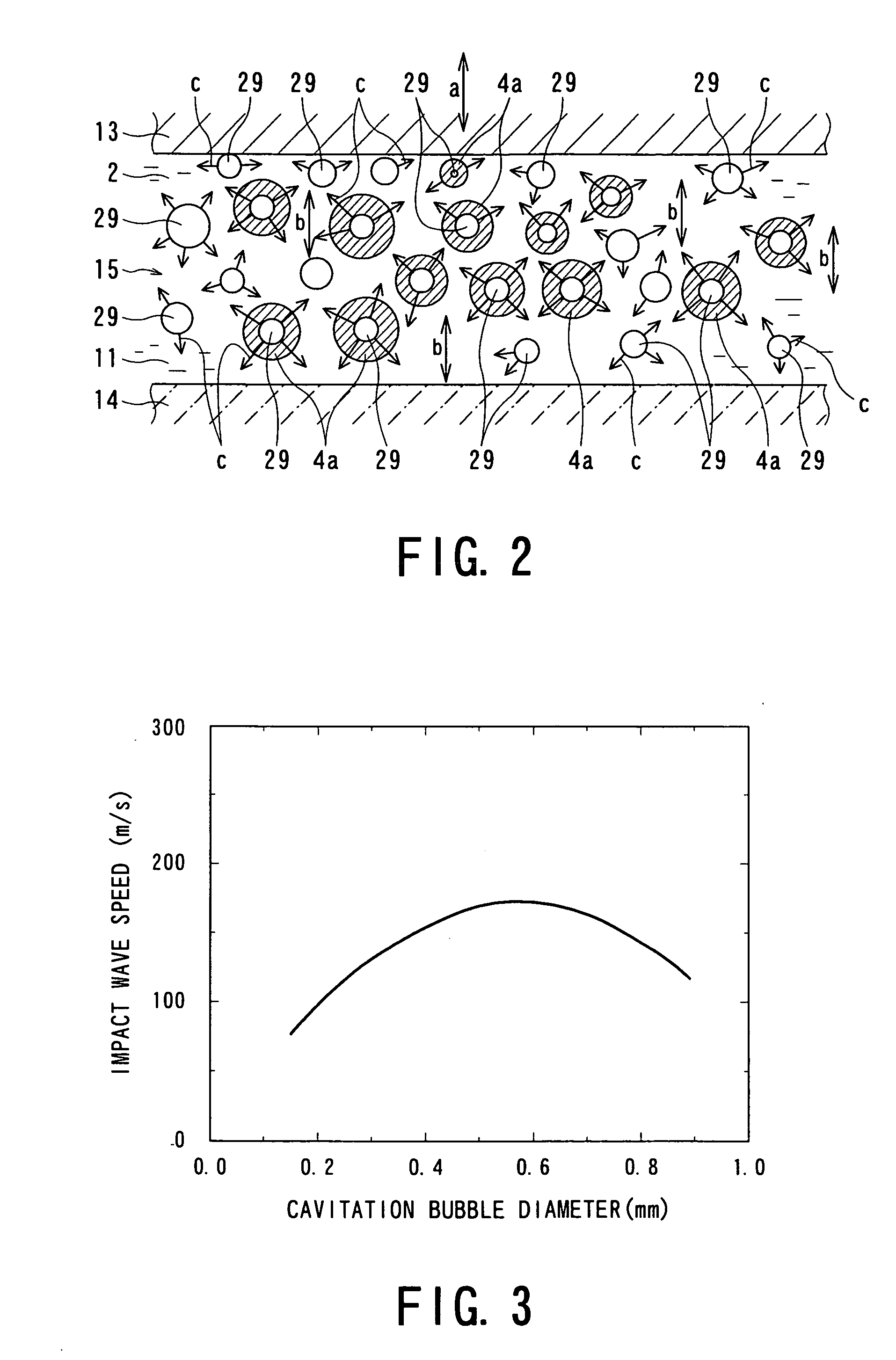
[0018] The inventors have investigated the mechanism of producing various types of liquid mixture having an ultra fine particle size. Examples of the liquid mixture include a liquid mixture obtained by mixing two or more liquid components, a liquid mixture obtained by mixing a liquid component and a gas component, a liquid mixture obtained by mixing a liquid component and a powder component, or a combination of some of those liquid mixtures. As a result, the inventors have found that if a vibrator vibrating at high frequency and a reflector for reflecting vibration transmitted from the vibrator to mixture components are arranged in a vessel for storing the mixture components with a narrow space existing between the vibrator and the reflector, an extremely-high cavitation effect can be achieved, whereby a liquid mixture having an ultra fine particle size, high mixture density, and high quality can be produced.
[0023] If the vibrator is vibrated at an ultrasonic frequency higher than or equal to 20 KHz, molecule clusters of, for example, liquid fuel are reduced in size due to the vibration. Thus, when the vibrator is ultrasonically vibrated, large molecular chains of the fuel are physically broken into smaller chains by the synergistic effect of the impact pressure of the cavitation and the decomposition of the clusters by the supersonic vibration, whereby the fuel is reformed. Large molecular chains of a liquid component are also broken into smaller chains by the shock waves created by the cavitation and the reflected waves. Therefore, liquid fuel is reformed to be more combustible.
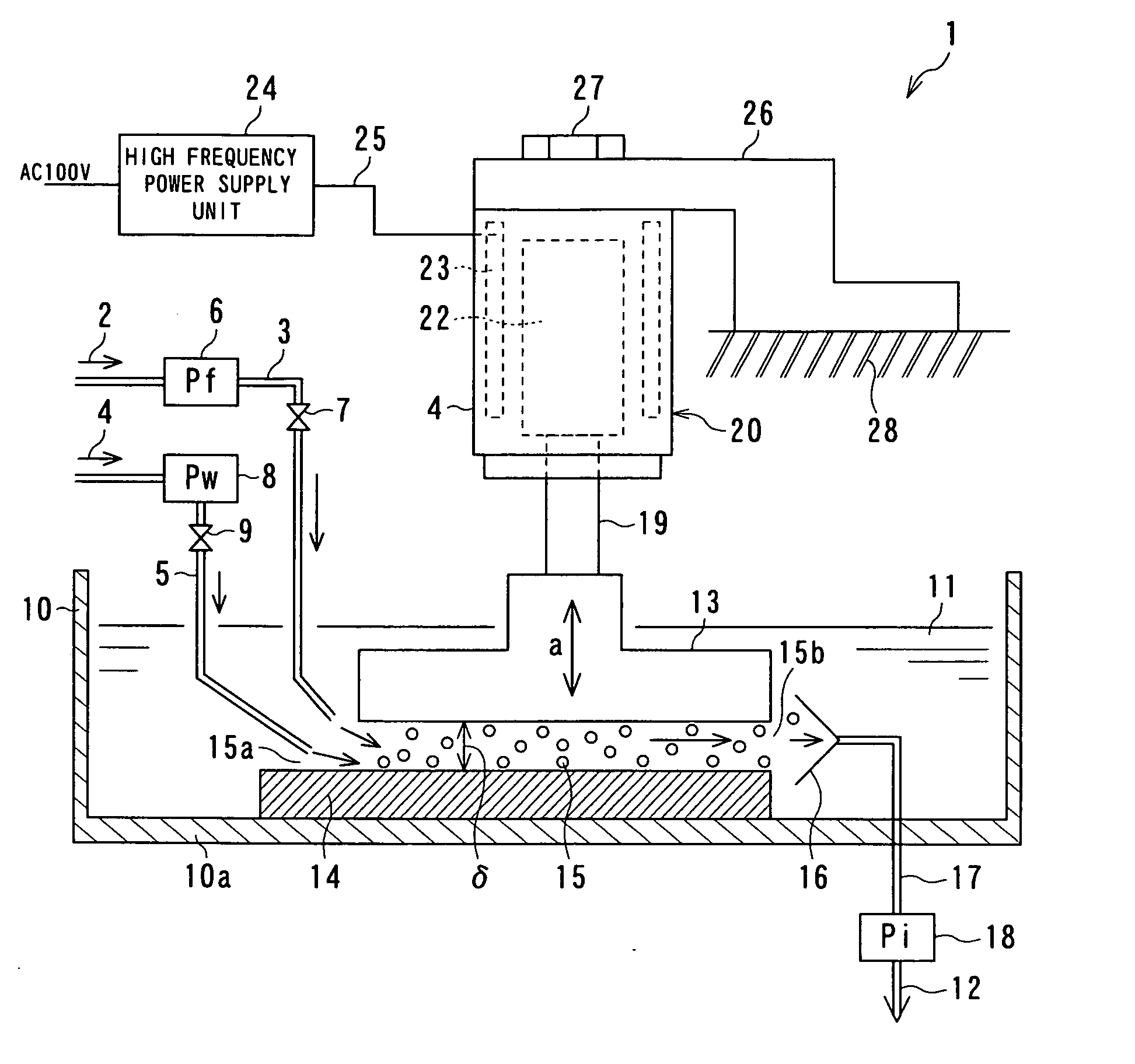
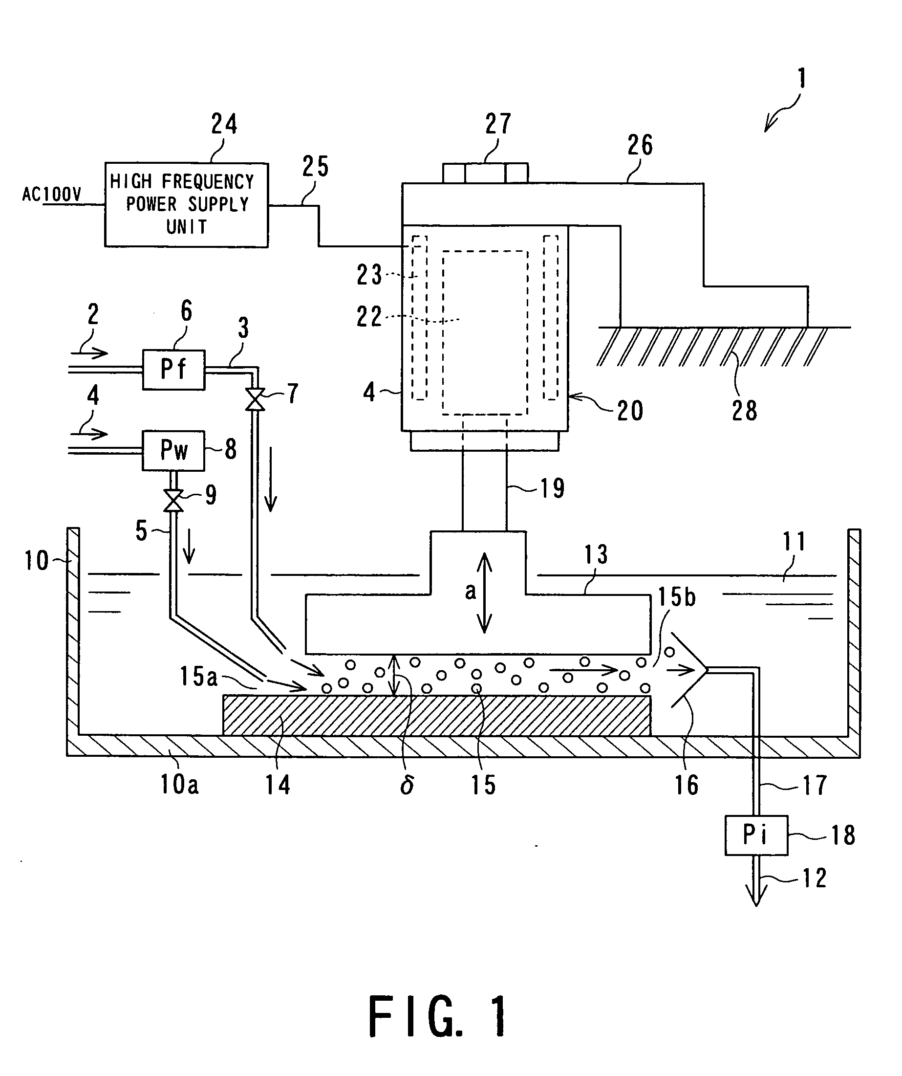
[0027] An apparatus according to the present invention has been developed based on the above findings and is usable to produce a liquid mixture obtained by mixing two or more liquid components, a liquid mixture obtained by mixing a liquid component and a gas component, a liquid mixture obtained by mixing a liquid component and a powder component, or a combination of some of those liquid mixtures. The liquid-mixing apparatus includes a vessel for storing the mixture components; a vibrator, placed in the vessel, having at least one surface with a predetermined area contacting the mixture components; a high-frequency vibration generator, connected to the vibrator, for vibrating the vibrator at high frequency in the direction perpendicular to the face; and a reflector which is placed in the vessel, which is spaced from the vibrator at a small distance in such a manner that the surface of the vibrator contacting the mixture components faces a surface of the reflector, and which reflects high-frequency vibration transmitted from the vibrator to create reflected waves in the mixture components flowing between the facing surfaces. The vibrator and the reflector cooperate to create cavitation bubbles in the mixture components using the decompression action of the vibrator allowed to move away from the reflector by the high-frequency vibration transmitted from the high-frequency vibration generator to the vibrator and also cooperate to break the cavitation bubbles using the compression action of the vibrator allowed to move toward the reflector, and shock wave energy generated by the breaking action extremely reduces the size of the cavitation bubbles and promotes the diffusion of the mixture components, whereby the liquid mixture is allowed to have an ultra fine particle size and high density.
[0041] The liquid-mixing method includes the steps of storing the mixture components in a vessel including a vibrator vibrating at high frequency and a reflector spaced from the vibrator at a small distance; creating cavitation bubbles in the mixture components flowing between the vibrator and the reflector using the decompression action of the vibrator allowed to move away from the reflector by high-frequency vibration transmitted from the high-frequency vibration generator to the vibrator; breaking the cavitation bubbles using the compression action of the vibrator allowed to move toward the reflector; reducing the size of the cavitation bubbles with shock wave energy generated due to the compression action; and promoting the diffusion of the mixture components to allow the liquid mixture to have an ultra fine particle size and high density.

Problems solved by technology

That is, emissions, such as NOx, unburned hydrocarbons, and particles, contained in exhaust gas cause air pollution to impair human health.
Diesel engine vehicles, particularly heavy-duty trucks, have a large piston displacement and therefore emit a large amount of exhaust gas from their engines.
Hence, exhaust gas-cleaning systems for these vehicles are large in size.
Furthermore, since chemical substances contained in the exhaust gas are trapped with micropore filters or catalysts, an increase in mileage causes clogging.
For such a screw-type agitating unit, there are problems in that the size thereof is large and it takes a long time to prepare the emulsion fuel.
Furthermore, for the emulsion fuel, there is a problem in that water and oil are separated from each other in a short time while the emulsion fuel is allowed to stand for a while because water clusters contained in the emulsion fuel have a large size.
In these uses, any liquid mixture with an ultra fine particle size and high mixture density has not been obtained.
For the known technique for mixing fuel such as gas oil with an incompatible liquid such as water to prepare an emulsion fuel, there are problems in that the apparatus is large in size because of the location of a screw-type agitating unit, it takes a long time to prepare the emulsion fuel, and water and oil in the emulsion fuel are separated from each other in a short time, as described above.
Therefore, this technique cannot be directly applied to diesel engines and combustion units such as boilers.
However, neither any system nor any method of efficiently achieving high energy is particularly disclosed in the above two documents relating to the utilization of cavitation effects.
However, any sufficient cavitation effect cannot be necessarily achieved and any liquid mixture with a fine particle size can hardly be prepared efficiently utilizing such a technique.
For a liquid mixture prepared by utilizing any one of the known techniques, there is a problem in that the quality of the mixture cannot be maintained for a long time because liquid components are readily separated from each other in a relatively short time as described above.
Any liquid mixtures for producing industrial materials such as ceramics, paste food products such as creams, cosmetic products, and drug products having an ultra fine particle size and high mixture density cannot be necessarily obtained by the known techniques, which cannot sufficiently cope with requirements such as an improvement in quality.
These mixtures prepared by the known techniques do not necessarily have an ultra fine particle size.

Method used


Image

  • Liquid mixing apparatus and method of liquid mixing
  • Liquid mixing apparatus and method of liquid mixing
  • Liquid mixing apparatus and method of liquid mixing

Examples


third embodiment (fig.9)

[Third Embodiment (FIG. 9)]

[0117] A third embodiment of the present invention provides a liquid-mixing apparatus and liquid-mixing method of mixing at least three liquids. FIG. 9 is an illustration showing a configuration of the liquid-mixing apparatus of the third embodiment. The configuration of this embodiment is substantially the same as that of the second embodiment except the arrangement of lines for supplying liquid mixture components. The same components shown in FIG. 9 as those shown in FIG. 6 have the same reference numerals and descriptions about the components are omitted.

[0118] With reference to FIG. 9, the apparatus of this embodiment includes a first tank 81, a second tank 82, and a third tank 91 acting as sources for supplying respective three different liquids.

[0119] The first tank 81 contains an oil fuel such as a fuel oil, a gas oil, a waste oil (for example, engine oil), or a waste edible oil.

[0120] The second tank 82 contains, for example, an oil other than t...

fourth embodiment (fig.10)

[Fourth Embodiment (FIG. 10)]

[0126] A fourth embodiment of the present invention provides a liquid-mixing apparatus and liquid-mixing method of producing a mixture containing a high-viscosity liquid. FIG. 10 is an illustration showing a configuration of the liquid-mixing apparatus of this fourth embodiment. The configuration of this embodiment is substantially the same as that of the second embodiment except an arrangement of lines for supplying liquid mixture components. The same components shown in FIG. 10 as those shown in FIG. 6 have the same reference numerals and descriptions about the components are omitted.

[0127] With reference to FIG. 10, the apparatus of this embodiment includes a first tank 81 and a second tank 82 acting as sources for supplying respective two different liquids.

[0128] The first tank 81, as well as that described in the second embodiment, contains an oil fuel such as a fuel oil, a gas oil, a waste oil (for example, an engine oil), or a waste edible oil. ...

fifth embodiment (fig.11)

[Fifth Embodiment (FIG. 11)]

[0133] A fifth embodiment of the present invention provides a liquid-mixing apparatus and liquid-mixing method of producing a creamy liquid mixture with a fine texture. FIG. 11 is an illustration showing a configuration of the liquid-mixing apparatus of this fifth embodiment. The configuration of this embodiment is substantially the same as that of the second embodiment except an arrangement of lines for supplying liquid mixture components. The same components shown in FIG. 11 as those shown in FIG. 6 have the same reference numerals and descriptions about the components are omitted.

[0134] With reference to FIG. 11, the apparatus of this fifth embodiment is provided with, for example, a first tank 81 and a second tank 82 acting as sources for supplying respective two different liquids and further includes an air supply line 95 for supplying air.

[0135] The first tank 81 contains a liquid component such as an edible oil, a cosmetic fat, or a medicated oil...


PUM

PropertyMeasurementUnit
Distanceaaaaaaaaaa
Timeaaaaaaaaaa
Sizeaaaaaaaaaa

Abstract

An apparatus includes a vessel 10 for storing a liquid mixture 11 containing a liquid fuel 2 and an incompatible liquid 4 such as water or for allowing the liquid mixture 11 to flow therethrough, a vibrator 13 having at least one portion making contact with the liquid mixture in the vessel, a vibration generator 20 for vibrating the vibrator at high frequency, and a reflector 14 spaced from the vibrator 13 at a small distance. The incompatible liquid 4 is dispersed in and mixed with the fuel 2 by vibrating the vibrator at high frequency, whereby an emulsion fuel 12 having an ultra fine particle size and high mixture density is produced. According to the above configuration, cavitation can be extremely efficiently generated. The following technique is disclosed: a technique for producing various types of liquid mixture having an ultra fine particle size using the cavitation efficiently. In particular, the following mixture can be produced in a short time with high efficiency: a liquid mixture, such as an emulsion fuel, a liquid industrial material, a food product, a cosmetic product, or a drug product, having an ultra fine particle size, high mixture density, and high quality. If the liquid mixture is stored over a long period of time, liquid components thereof are hardly separated from each other.

Description

TECHNICAL FIELD [0001] The present invention relates to techniques for mixing various liquids, which is useful in producing various liquid mixtures such as fuel products, industrial materials, food products, cosmetic products and drug products, and particularly relates to an apparatus for mixing liquids and a method of mixing such liquids, which are useful in producing a liquid mixture with ultra-fine particle size and high mixture density effectively utilizing a cavitation effect. BACKGROUND ART [0002] In general, diesel engine vehicles run on gas fuel. Recently, the following problem has become a matter of public concern. That is, emissions, such as NOx, unburned hydrocarbons, and particles, contained in exhaust gas cause air pollution to impair human health. [0003] Therefore, various techniques have been developed to clean exhaust gas from diesel engines. The amount of emitted NOx and particulates are reduced with, for example, ceramic filters or special catalyst devices attached...

Claims


Application Information

Patent Timeline
IPC IPC(8): B01F23/47F02M27/08
CPCB01F3/0819B01F11/0258F02M25/0228F02M27/08Y02T10/121F02M25/0225Y02T10/12B01F23/4111B01F31/85
Inventor OOGAWARA, TAKASHIHIROTA, GOICHINISHIYAMA, KATSUJI
Owner TOSHIBA PLANT SYSTEMS & SERVICES
Learn More