
Led array systems

a technology of array systems and led arrays, applied in the direction of identification means, lighting and heating apparatus, instruments, etc., can solve the problems of inherently inefficient manufacturing, relatively thick array tiles, and bulky bulky structures

Inactive Publication Date: 2005-12-01
3M INNOVATIVE PROPERTIES CO
View PDF27 Cites 396 Cited by
  • Summary
  • Abstract
  • Description
  • Claims
  • Application Information

AI Technical Summary

Benefits of technology

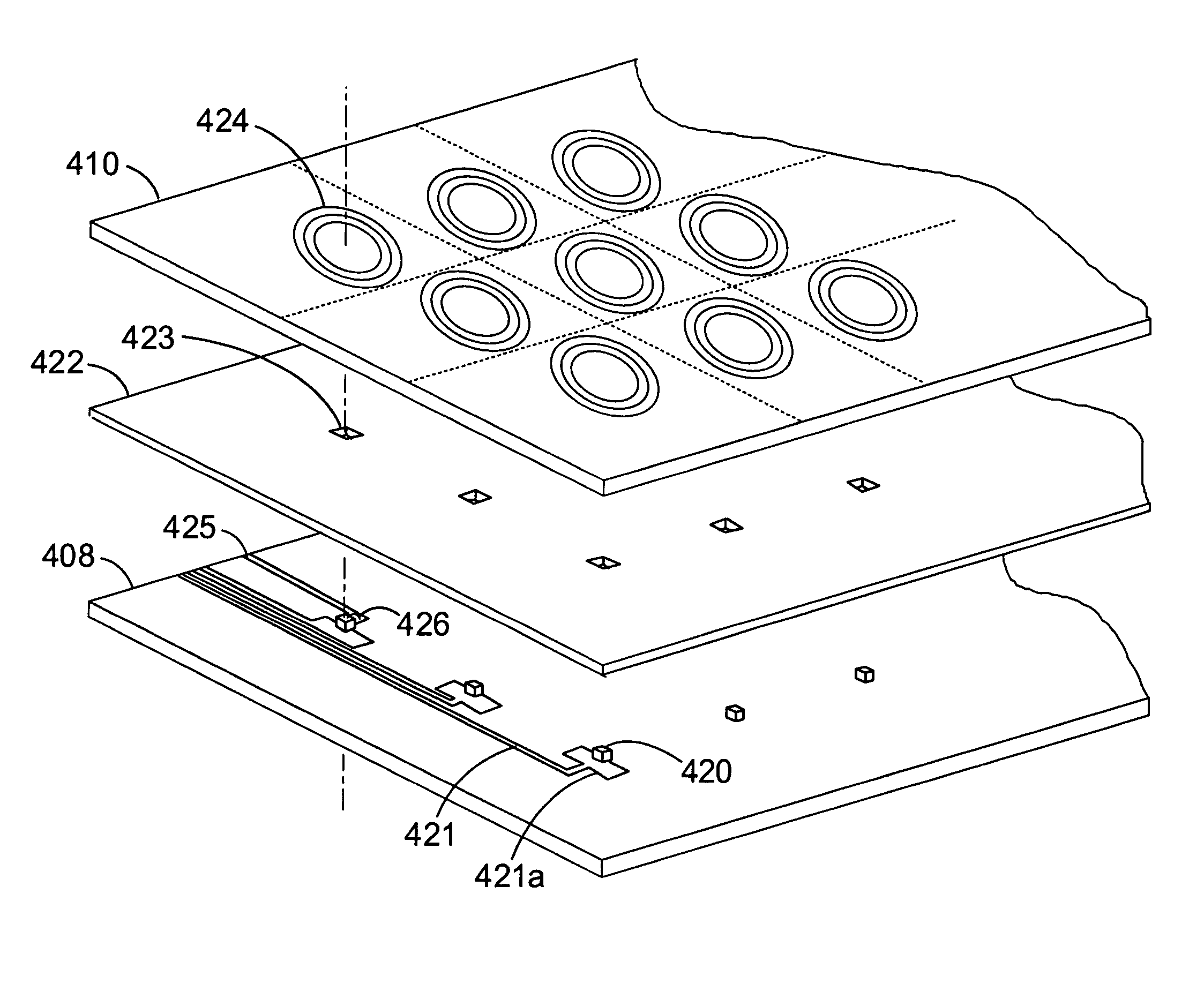
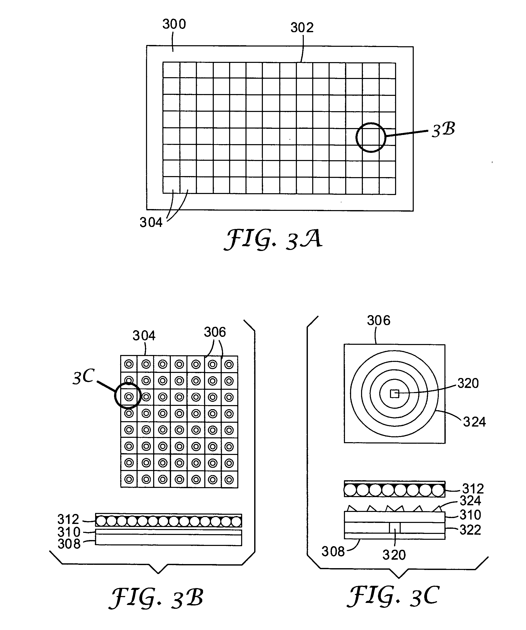
The invention described in this patent is useful for making LED arrays for lighting and display purposes. It includes an optical assembly with LEDs mounted on a substrate, an optical sheet over the LEDs, and a light spreader sheet over the LEDs. The light spreader sheet has features that direct the spread light out of it. Another embodiment includes an array of LEDs emitting light in a direction perpendicular to the substrate, and a reflector sheet with reflectors and a screen layer. The reflectors have apertures, and the LEDs protrude through them. The invention also includes an assembly with LEDs and reflectors positioned on a substrate, and a screen layer on the other side of the reflector sheet. Overall, the invention provides improved methods for emitting light from LED arrays.

Problems solved by technology

Manufacturing is inherently inefficient due to the separate packaging and array population steps and the optics suffer due to the nature of the point source within an extended array.
Furthermore, the resulting array tile is relatively thick and bulky.

Method used


Image

  • Led array systems
  • Led array systems
  • Led array systems

Examples


example 1

Ceiling Lighting

[0114] This example considers a lighting fixture having a diagonal of 70″ (178 cm) and an aspect ratio of 5:1. The example considers the design of a fixture that provides light equivalent to 2 fluorescent tubes at 70 L / W and using 100 W input power, or 7000 Lumens.

[0115] The assumed LED characteristics are as shown in Table I. The characteristics are similar to those for a 1 mm square Luxeon white LED available from Lumileds Lighting LLC, San Jose, Calif.

[0116] The LEDs are assumed to be driven at ⅔ maximum rated power, hence the actual current is less than the maximum current. The calculated lighting unit design is summarized in Table 1.

TABLE ILED CharacteristicsWavelength bandWhiteLuminous efficacy (L / W)25Max. forward current (mA)350Max. power (W)1.19Power consumed (W)0.80Actual forward current (mA)235Forward voltage (V)3.4Light out (L)20.0

[0117]

TABLE IILighting Unit CharacteristicsLightguide extraction / absorption factor (%)80LED coupling to LG (%)95Net effici...

example 2

RGB Backlight for a Liquid Crystal Display

[0119] In this example, the lighting unit is used as the backlight for a liquid crystal display (LCD) having a diagonal of 23″. Each light emitting element includes four LED dies, one red, two green and one blue. Active control of the different LED dies permits for control of the backlight color. In the example design, the backlight has a color temperature of 6500 K.

TABLE IIILED Characteristics for BacklightTotalNumber / color triad1214Wavelength bandRedGreenBlueLuminous efficacy (L / W)4023518.81Max. forward current (mA)385700350Max. power (W)1.142.391.24.73Actual forward current (mA)126505320Power consumed (W)0.371.731.093.19Forward voltage (V)2.953.423.42Light out (L)14.8339.705.4760% of luminous content24.766.29.1Color temperature (K)6500

[0120] The lighting unit is assumed to use a single sheet of brightness enhancing film and to produce a horizontal viewing angle of 56° (half maximum, half angle) and a vertical viewing angle of 37° (half...


PUM

PropertyMeasurementUnit
color rendering indexaaaaaaaaaa
thicknessaaaaaaaaaa
thickaaaaaaaaaa

Abstract

A light emitting diode (LED) array comprises an array of LEDs mounted to a substrate. The LEDs emit light in a direction generally perpendicular to the substrate. An optical sheet is disposed over the LEDs. At least a portion of light entering one side of the optical sheet from the LEDs is guided within the optical sheet in a direction generally parallel to the substrate. Light extraction features direct light from the optical sheet in a generally forward direction. Such an array is useful for several applications, including space lighting, direct information display and backlighting of liquid crystal displays. The light spreading effect of the optical sheet reduces the amount of black space between LED pixels.

Description

FIELD OF THE INVENTION [0001] The invention relates to lighting or display assemblies, and more particularly relates to lighting or display assemblies that use arrays of light emitting diodes (LEDS). BACKGROUND [0002] LED arrays are typically formed using LEDs that have a polymer encapsulant formed over an LED die and an associated reflector cup. The LED die itself has a quasi-Lambertian emission pattern and much of the light generated within the LED die is trapped due to total internal reflection at the die surface or emitted from the edge. The polymer encapsulant is shaped to extract more light and to focus the extracted light into a preferred emission profile. The reflector cup captures edge-emitted light and bends it forwards. The array, commonly formed as a tile, may also have side reflectors. The total effect of the reflectors and the encapsulant controls the optical profile of the LED pixel in the array. [0003] Traditionally, the manufacture of a LED array thus includes steps...

Claims


Application Information

Patent Timeline
Patent Type & Authority Applications(United States)
IPC IPC(8): F21V8/00G02B6/00G02F1/13357G09F9/33G09F9/35H01L33/48H01L33/58H01L33/60H01L33/62
CPCG02B3/0056G02B6/0018G02B6/0021G02B6/0053G09F9/3026G02B6/0068G02F1/133603G09F9/33G09F9/35G02B6/0055
Inventor EPSTEIN, KENNETH A.TRAN, HUNG T.SCHULTZ, JOHN C.EMMONS, ROBERT M.
Owner 3M INNOVATIVE PROPERTIES CO
Learn More