
Magnetic recording head with reduced thermally induced protrusion

a magnetic recording and thermally induced protrusion technology, applied in the field of magnetic recording heads, can solve the problems of enlarge the head, disrupt the airflow over the head, and the recording head cannot be changed in the desired shape, so as to prevent the degradation of toughness of the layer, prevent surface defects, and reduce the stress intensity factor

Inactive Publication Date: 2005-12-01
HITACHI GLOBAL STORAGE TECH NETHERLANDS BV
View PDF21 Cites 0 Cited by
  • Summary
  • Abstract
  • Description
  • Claims
  • Application Information

AI Technical Summary

Benefits of technology

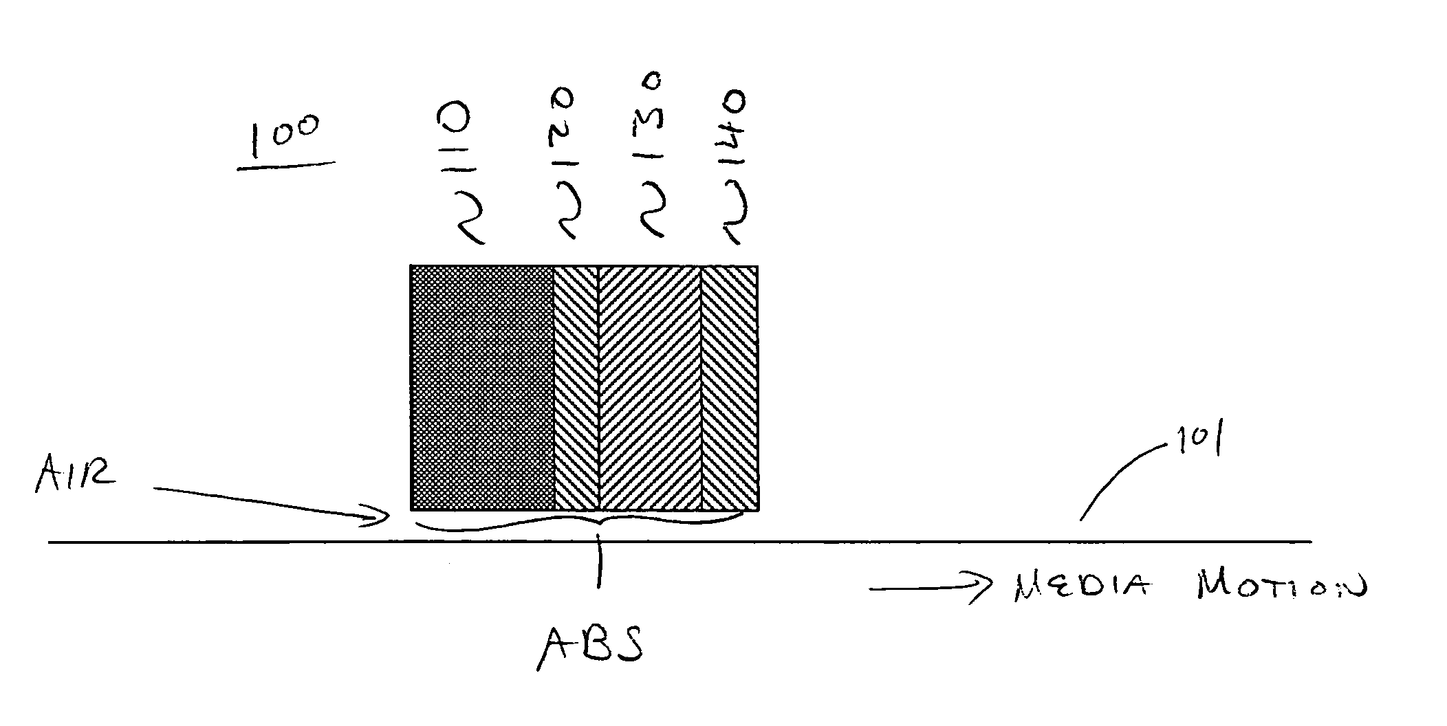
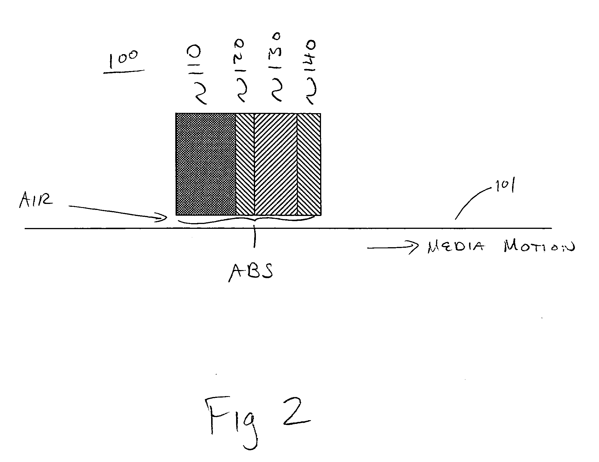
[0011] Accordingly, a novel magnetic recording head with reduced thermally induced protrusion is disclosed. In one embodiment, a thermal expansion constraining layer comprising silicon dioxide for instance overlays a magnetic recording head. The thermal expansion constraining layer has a very low coefficient of thermal expansion. A sealant layer comprising aluminum oxide overlays the thermal expansion constraining layer. The thermal expansion constraining layer prevents deleterious deformation of underlying head structures that can degrade performance of a storage system. The sealant layer protects the thermal expansion constraining layer from propagation of surface defects therein by protection from shock, including shock during fabrication, as well as moisture, increasing manufacturing yield and reliability.
[0013] In accordance with embodiments of the present invention, a sealant layer serves to prevent surface defects of a thermal expansion constraining layer from exposure to water and / or moisture, e.g., due to cleaning operations during fabrication. Reduced water / moisture exposure serves to prevent thermal expansion constraining layer fracture toughness degradation, and to provide reduced stress intensity factor from a constraining effect of a sealant layer, which will reduce driving forces for crack propagation. Both characteristics serve to increase chip and crack resistance during fabrication. To further increase fracture resistance and constraint to thermal protrusion, a multilayer laminate may be utilized to maximize such benefits.

Problems solved by technology

Unfortunately, in many modern head assemblies, thermal expansion due to heating resulting from a write current can cause a highly undesirable change in shape of the recording head.
Such shape changes can enlarge the head and / or disrupt airflow over the head.
Such shape changes will generally cause undesirable changes in head flying height.
For example, if the head flys too high as a result of such a shape change, a write operation performed at such time may write too wide a track, damaging adjacent stored information.
Additionally, too high a flying height may result in weakly recorded signals.
By way of further example, flying too low, e.g., too close to a recording media is also undesirable.
Flying below a desirable height can cause overly strong recorded signals.
Additionally, heads that are flying too low may not be able to clear, e.g., fly over, small particles, e.g., dust, that are present within the head disk enclosure, potentially causing damage to the head and / or media.
An additional ever-present danger of heads flying too low is that the head can “crash” onto the media surface.
Such a head crash can severely damage both head and media, leading to a catastrophic loss of stored data.
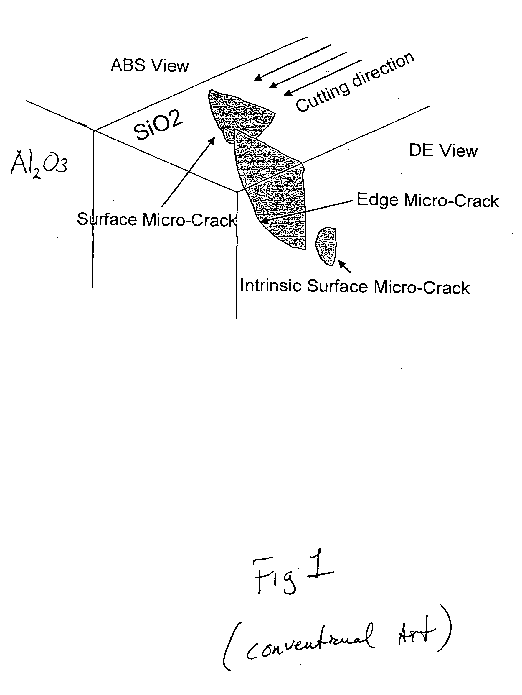
Unfortunately, silicon dioxide has a lower fracture toughness than aluminum oxide, e.g., SiO2 cracks more easily than Al2O3, and moisture in known to embrittle silicon dioxide.
For example, surface defects in the form of micro-cracks can form on the surface creating by cutting.
Such micro-cracks can take the form of edge cracks and surface cracks.
Water-based cleaning during processing tends to make such coatings more brittle and encourage more cracking, as well as propagating existing cracks.

Method used


Image

  • Magnetic recording head with reduced thermally induced protrusion
  • Magnetic recording head with reduced thermally induced protrusion
  • Magnetic recording head with reduced thermally induced protrusion

Examples


Embodiment Construction

[0018] In the following detailed description of the present invention, magnetic recording head with reduced thermally induced protrusion, numerous specific details are set forth in order to provide a thorough understanding of the present invention. However, it will be recognized by one skilled in the art that the present invention may be practiced without these specific details or with equivalents thereof. In other instances, well-known methods, procedures, components, and circuits have not been described in detail as not to unnecessarily obscure aspects of the present invention.

Magnetic Recording Head with Reduced Thermally Induced Protrusion

[0019] Embodiments in accordance with the present invention relate to the field of data storage devices. More specifically, embodiments in accordance with the present invention relate to magnetic recording heads, e.g., for use in data storage disk drive systems. It is to be appreciated, however, that embodiments in accordance with the present...


PUM

PropertyMeasurementUnit
coefficient of thermal expansionaaaaaaaaaa
thermal expansionaaaaaaaaaa
shock resistanceaaaaaaaaaa

Abstract

A magnetic recording head with reduced thermally induced protrusion. In one embodiment, a thermal expansion constraining layer comprising silicon dioxide for instance overlays a magnetic recording head. The thermal expansion constraining layer has a very low coefficient of thermal expansion. A sealant layer comprising aluminum oxide overlays the thermal expansion constraining layer. The thermal expansion constraining layer prevents deleterious deformation of underlying head structures that can degrade performance of a storage system. The sealant layer protects the thermal expansion constraining layer from propagation of surface defects therein by protection from shock, including shock during fabrication, as well as moisture, increasing manufacturing yield and reliability.

Description

FIELD OF THE INVENTION [0001] Embodiments in accordance with the present invention relate to the field of data storage devices. More specifically, embodiments in accordance with the present invention relate to magnetic recording heads. BACKGROUND [0002] A disk storage system, such as a magnetic hard disk drive (HDD), uses one or more disks or “platters” as a data recording medium. The HDD records data on the disk by use of a magnetic recording head which can also reproduce data from the disk. [0003] The recording or read / write heads of modern hard disk drives do not actually make contact with the recording media. Rather the heads “fly” on a cushion of air generated by the relative motion of the head over a rapidly spinning platter or disk comprising the recording media. The “face” of the recording head adjacent to the disk is known as the air bearing surface, or ABS. The ability of a head to fly at a desirable height is a critical performance aspect of hard disk drives. [0004] Incre...

Claims


Application Information

Patent Timeline
Patent Type & Authority Applications(United States)
IPC IPC(8): G11B5/147G11B5/187G11B5/31
CPCG11B5/187G11B5/3136G11B5/3133G11B5/3106
Inventor SHI, NINGWU, XIAOZHANG, HONG
Owner HITACHI GLOBAL STORAGE TECH NETHERLANDS BV
Learn More