
Estimation and resolution of carrier wave ambiguities in a position navigation system

a position navigation system and carrier wave technology, applied in wave based measurement systems, direction/deviation determining electromagnetic systems, instruments, etc., can solve problems such as the inability to measure the integer number of cycles of incoming satellite signals, the difference in the phase delay of a carrier signal received by the base and rover receivers may substantially exceed one cycle, and the resolution of ambiguity problems, to achieve the effect of improving the accuracy of determination

Active Publication Date: 2005-12-01
TOPCON GPS
View PDF16 Cites 24 Cited by
  • Summary
  • Abstract
  • Description
  • Claims
  • Application Information

AI Technical Summary

Benefits of technology

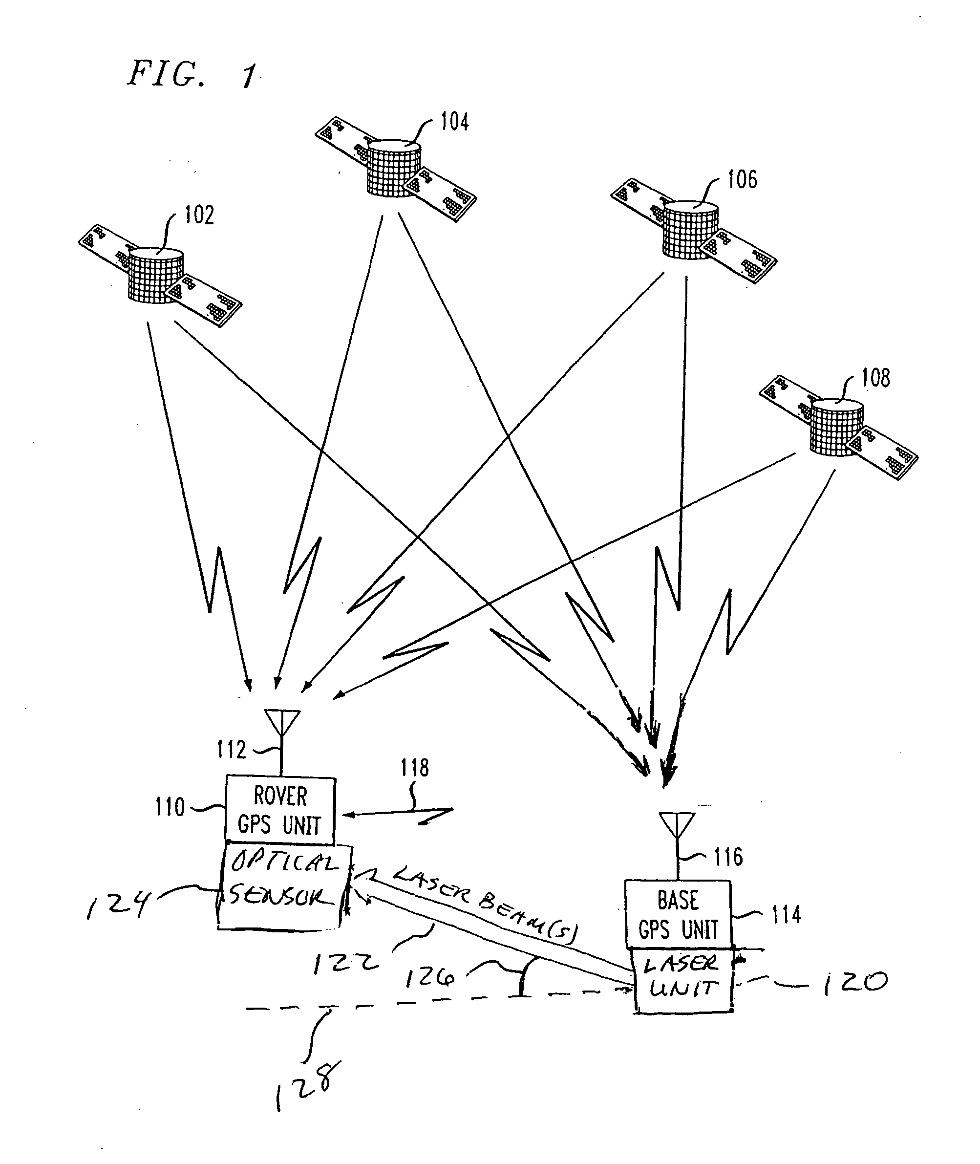
"The present invention provides a better method and apparatus for accurately determining the position of a stationary or moving object using navigation satellite signals, receiver time offsets, laser beam transmitters, and laser beam receivers. One aspect of the invention is speeding up the resolution of carrier phase ambiguity in satellite position navigation systems by using laser beam angle measurements. This technique helps resolve carrier wave phase ambiguities and minimize errors in determining the location of the rover. The invention uses a geometric constraint based on the elevation angle between the base and rover, along with other parameters and calculations for estimation and resolution of floating point and integer carrier phase ambiguity estimation and resolution. Overall, the invention improves the accuracy of positioning and navigation."

Problems solved by technology

The practical implementation of those advantages, which might otherwise be guaranteed by the measurement of the carrier phases, runs into the problem of ambiguity resolution for phase measurements.
Therefore, the difference in the phase delays of a carrier signal received by the Base and Rover receivers may substantially exceed one cycle.
Second, it is not possible to measure the integer number of cycles from the incoming satellite signals; one can only measure the fractional part.
However, the task of measuring carrier phase is difficult to accomplish.
In practice, we must use non-ideal receivers to measure the phases, with each receiver having a different clock offset with respect to the GPS time, and with each receiver having phase errors occurring during the measurement process.
In addition, at the present time it is not practical to individually count the carrier cycles as they are received by the receiver's antenna since the frequency of the carrier signal is over 1 GHz.

Method used


Image

  • Estimation and resolution of carrier wave ambiguities in a position navigation system
  • Estimation and resolution of carrier wave ambiguities in a position navigation system
  • Estimation and resolution of carrier wave ambiguities in a position navigation system

Examples


Embodiment Construction

[0032] A typical exemplary position navigation system for implementing the features of the invention includes multiple satellites each radiating signals in two frequency bands: the L1 band and the L2 band. Two carrier signals are simultaneously transmitted in the L1-band; both carrier signals have the same frequency, but are shifted in phase by π / 2 (90°). The first L1 carrier signal is modulated by the clear acquisition C / A-code signal and the second L1 carrier signal is modulated by the precision P-code signal. One carrier signal is transmitted in the L2 band, and uses a different frequency than the L1 carrier signals. The L2 carrier signal is modulated by the same P-code signal used to modulate the second L1 carrier signal. These carrier frequencies are between 1 GHz and 2 GHz in value. Each C / A-code signal and P-code signal comprises a repeating sequence of segments, or “chips”, where each chip is of a predetermined time period and has a pre-selected value, which is either +1 or ...


PUM


Abstract

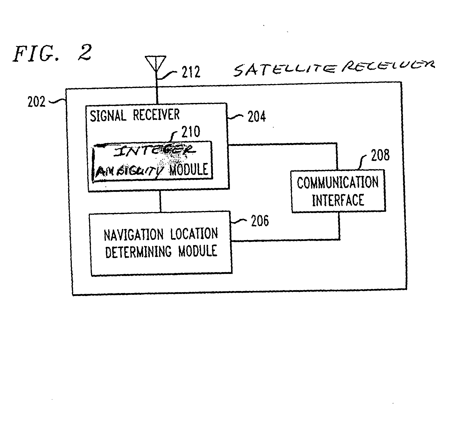
A method and apparatus for resolving floating point and integer ambiguities in a satellite position navigation system is disclosed. A rover station is periodically positioned at unknown locations and has a satellite receiver capable of receiving the navigation signals. By calculating relative position coordinates between a base station in a known location and the rover station, and by calculating other position parameters relative to the satellite position, a geometric constraint based on a measured elevation angle between the rover and base station can be incorporated into data computations and processing to help resolve carrier phase ambiguities. The elevation angle is measured by transmitting multiple laser beams to an optical sensor on the rover station. This technique results in greater precision in determining the location of the rover.

Description

BACKGROUND OF THE INVENTION [0001] This invention relates generally to satellite navigation receivers and more particularly to estimating and resolving integer and floating point ambiguities of a navigation satellite carrier wave. [0002] Satellite navigation systems, such as GPS (USA) and GLONASS (Russia), are well known in the art and are intended for highly accurate self-positioning of users possessing special navigation receivers. A navigation receiver receives and processes radio signals transmitted by satellites located within line-of-sight distance of the receivers. The satellite signals comprise carrier signals that are modulated by pseudo-random binary codes. The receiver measures the time delay of the received signal relative to a local reference clock or oscillator. These measurements enable the receiver to determine the so-called pseudo-ranges between the receiver and the satellites. The pseudo-ranges are different from the actual ranges (distances) between the receiver a...

Claims


Application Information

Patent Timeline
Patent Type & Authority Applications(United States)
IPC IPC(8): G01C15/00G01S19/44G01C25/00G01S3/782G01S5/00G01S5/14
CPCG01C15/002G01S19/44G01S3/782
Inventor BRABEC, VERNON JOSEPHGOAD, CLYDE C.KHVALKOV, ALEXANDER A.RAPOPORT, LEV BORISOVICH
Owner TOPCON GPS
Learn More