
Systems and methods for wireless network range extension

Active Publication Date: 2005-11-17
HONG KONG APPLIED SCI & TECH RES INST
View PDF20 Cites 100 Cited by
  • Summary
  • Abstract
  • Description
  • Claims
  • Application Information

AI Technical Summary

Benefits of technology

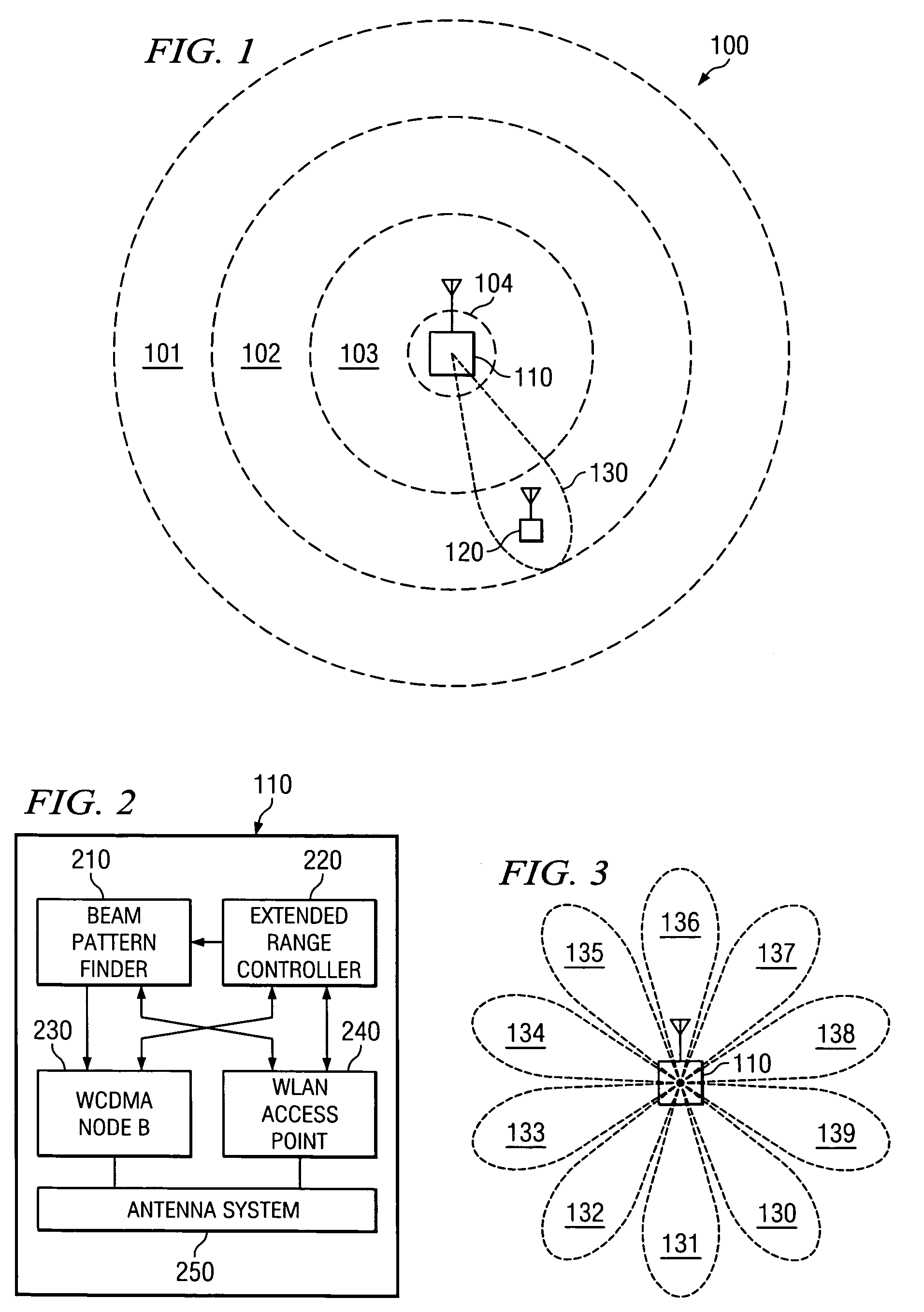
[0013] Secondary control channel signaling may be relatively low bandwidth and may be utilized to identify the need to communicate data, to identify a “best” directional antenna beam through which to communicate data, etcetera. Payload data may then be transmitted at a high bit rate through one or more smart antenna beams targeted at the appropriate stations. Accordingly, conventional cellular coverage or extended range mode coverage in combination with a dual mode remote station may be utilized according to embodiments of the present invention to expand the operating range of WLAN systems to the range of underlying cellular coverage.

Problems solved by technology

For example, there is a distance from a transmission source (e.g., transmitting antenna) at which the RF signal level falls below a certain threshold and cannot be usefully received.
When a station moves outside the coverage area signals cannot be received and communication is not possible.
It is a challenging problem to extend the coverage area of a WLAN system to provide high bandwidth coverage in outdoor public areas.
However, the use of repeaters in providing extended coverage areas is not without problems.
One of the significant problems for repeaters is that of feedback (i.e., some signals from the transmitter are fed back to the receiver of the repeater) causing the system to oscillate.
If a protocol allowing simultaneous up-link and down-link transmission, such as a carrier sense multiple access / collision avoidance (CSMA / CA) protocol were used, the system of Niki would experience an increased chance of oscillation.
Accordingly, the foregoing relay system configurations are not well suited for use with respect to a wide variety of communications protocols, particularly those commonly used with respect to WLANs (e.g., those implementing CSMA / CA protocols and / or time division duplexing (TDD)).
However, such cellular systems have heretofore provided such data communications with data rates much lower than those expected using WLAN communications.

Method used


Image

  • Systems and methods for wireless network range extension
  • Systems and methods for wireless network range extension
  • Systems and methods for wireless network range extension

Examples


Embodiment Construction

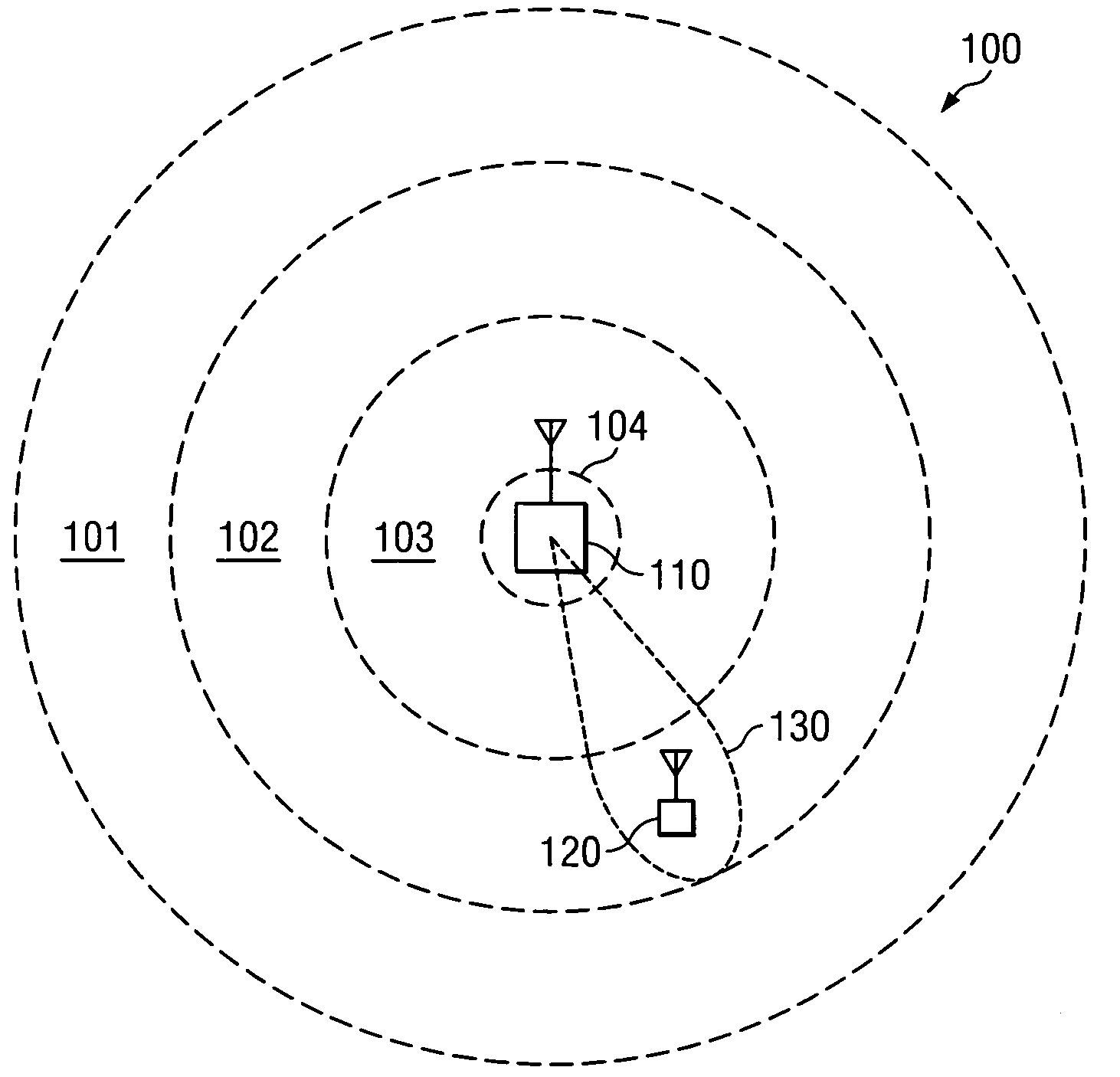
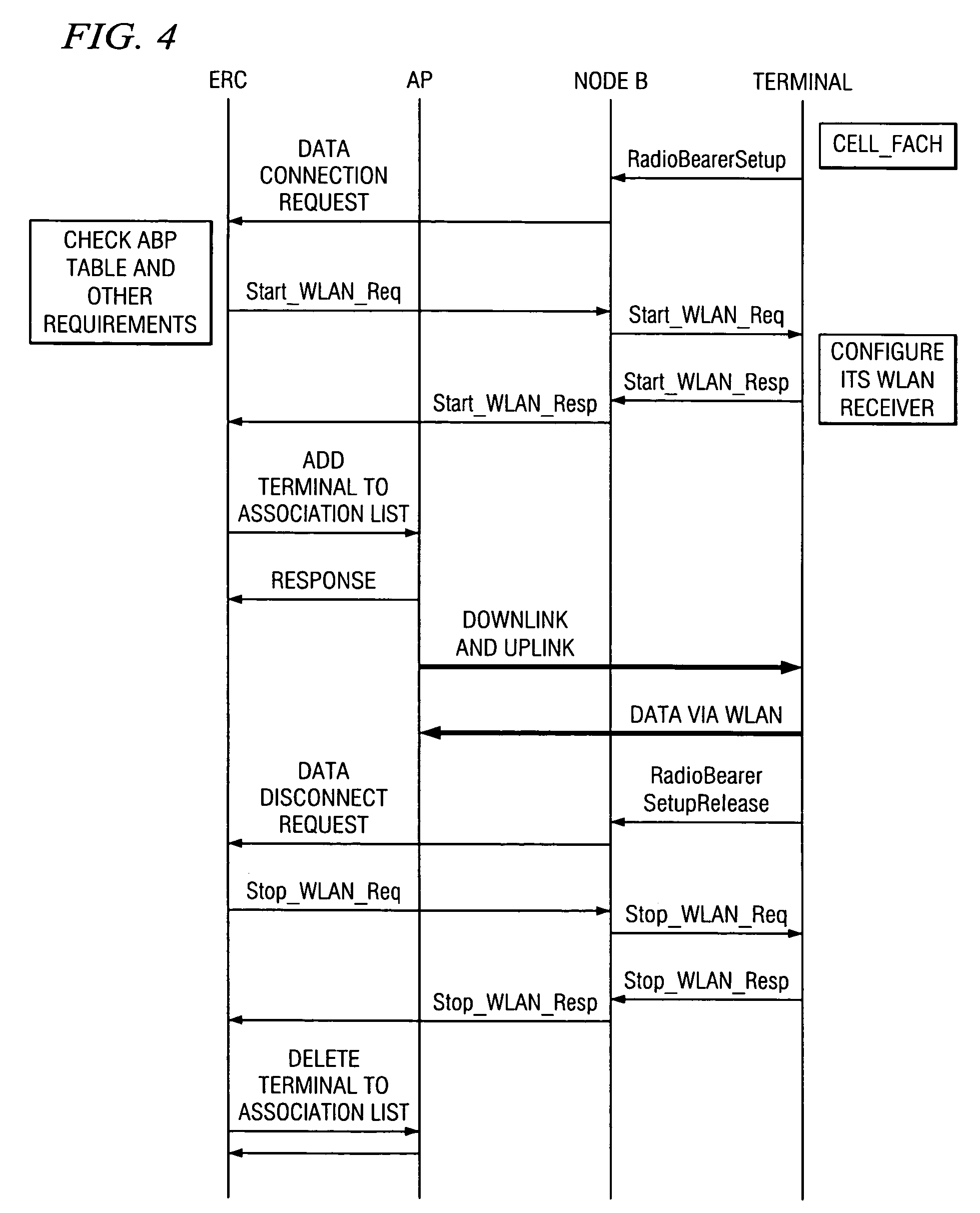
[0023] Embodiments of the present invention provide high bandwidth data communication within a large coverage area using smart antenna and / or directional antenna techniques and secondary control channel or out of band signaling (by out of band signaling it is meant in this context that the signaling is outside of the high bandwidth data communication, although the same frequency, protocol, etcetera may be used). For example, a larger or extended WLAN coverage area may be provided according to the present invention using a controllable directional antenna configuration, with the cooperation of a cellular system or a WLAN system adapted according to the present invention to perform best antenna beam pattern estimation and signaling. In operation according to such an embodiment, a station disposed within the coverage area of the WLAN infrastructure (WLAN coverage area) may operate in a substantially conventional manner to communicate with an access point using high data rate links. Sta...


PUM


Abstract

Disclosed are systems and methods which provide high bandwidth data communication with respect to a large coverage area using smart antenna and / or directional antenna techniques. Embodiments provide extended wireless local area network (WLAN) coverage areas using a directional antenna, with the cooperation of a cellular system or proprietary WLAN infrastructure to perform best antenna beam pattern estimation and signaling. Stations disposed beyond a WLAN coverage area may establish contact and exchange signaling information with an access point through a secondary control channel. Such a secondary control channel signaling may be relatively low bandwidth and may be utilized to identify the need to communicate data, to identify a “best” directional antenna beam through which to communicate data, etcetera. Payload data may then be transmitted at a high bit rate through one or more smart antenna beams targeted at the appropriate stations.

Description

CROSS-REFERENCE TO RELATED APPLICATIONS [0001] The present application is related to co-pending and commonly assigned U.S. patent application Ser. No. 10 / 778,923 entitled “Busy Tone For Wireless Networks,” filed Feb. 13, 2004, and Ser. No. 10 / 348,843 entitled “Wireless Local Area Network Time Division Duplex Relay System with High Speed Automatic Up-Link and Down-Link Detection,” filed Jan. 22, 2003, the disclosures of which are hereby incorporated herein by reference.TECHNICAL FIELD [0002] The present invention is related generally to wireless communications and, more particularly, to providing wireless communications with extended range. BACKGROUND OF THE INVENTION [0003] Wireless communication systems typically have a base station or access point from which radio signals are transmitted and propagate. These signals are then received by a mobile station, remote station, user station, etcetera (referred to herein collectively as station) allowing communication to proceed. Stations ...

Claims


Application Information

Patent Timeline
IPC IPC(8): H04B1/06H04B7/155H04B7/26
CPCH04B7/2606
Inventor WONG, CHEONG-YUILAU, VINCENTLIEW, SOUNG C.WONG, PUI BILL
Owner HONG KONG APPLIED SCI & TECH RES INST
Learn More