Method and apparatus for heating plastic extruding die
a technology of extruding dies and heating methods, which is applied in the direction of dough extruding machines, dough shaping, manufacturing tools, etc., can solve the problems of difficult cooling high temperature of the base of the nozzle, and the likelihood of the nozzle getting cool, so as to prolong the life of the coil (2), and avoid the effect of injuring the endurance of the coil
- Summary
- Abstract
- Description
- Claims
- Application Information
AI Technical Summary
Benefits of technology
Problems solved by technology
Method used
Image
Examples
first embodiment
[0048]FIG. 1 is a longitudinal sectional view of the plastic extruder according to the first embodiment of this invention. FIG. 2 is a cross sectional view taken in line II-II in FIG. 1.
[0049] In a plastic extruder 100 as shown, using a screw 22, an extruding unit 20 kneads the raw material pellet and additive supplied from a feeder not shown while they are heated and molten by a heater 21, and sends them to a plastic extruding die 10.
[0050] The plastic extruding die 10 extrudes molten resin in a stick shape from a large number of nozzles 1.
[0051] A cutting unit 30 cuts the stick-shaped resin extruded from the plastic extruding die 10 using a cutting blade 31. The resin is cooled by warm water to be formed in a resin pellet.
[0052] A coil 2 accommodated in a coil case 6 is provided around the nozzles 1 of the plastic extruding die 10.
[0053] The coil 2 is made by winding a conductive tube 4 by one turn, and surrounds only the tip of the nozzles 1.
[0054] Further, outside the coil...
second embodiment
[0066] Another coil which surrounds only the base of the nozzles 1 may be added. In this case, this coil is driven by lower electric power than the coil which surrounds only the tip of the nozzles 1.
third embodiment
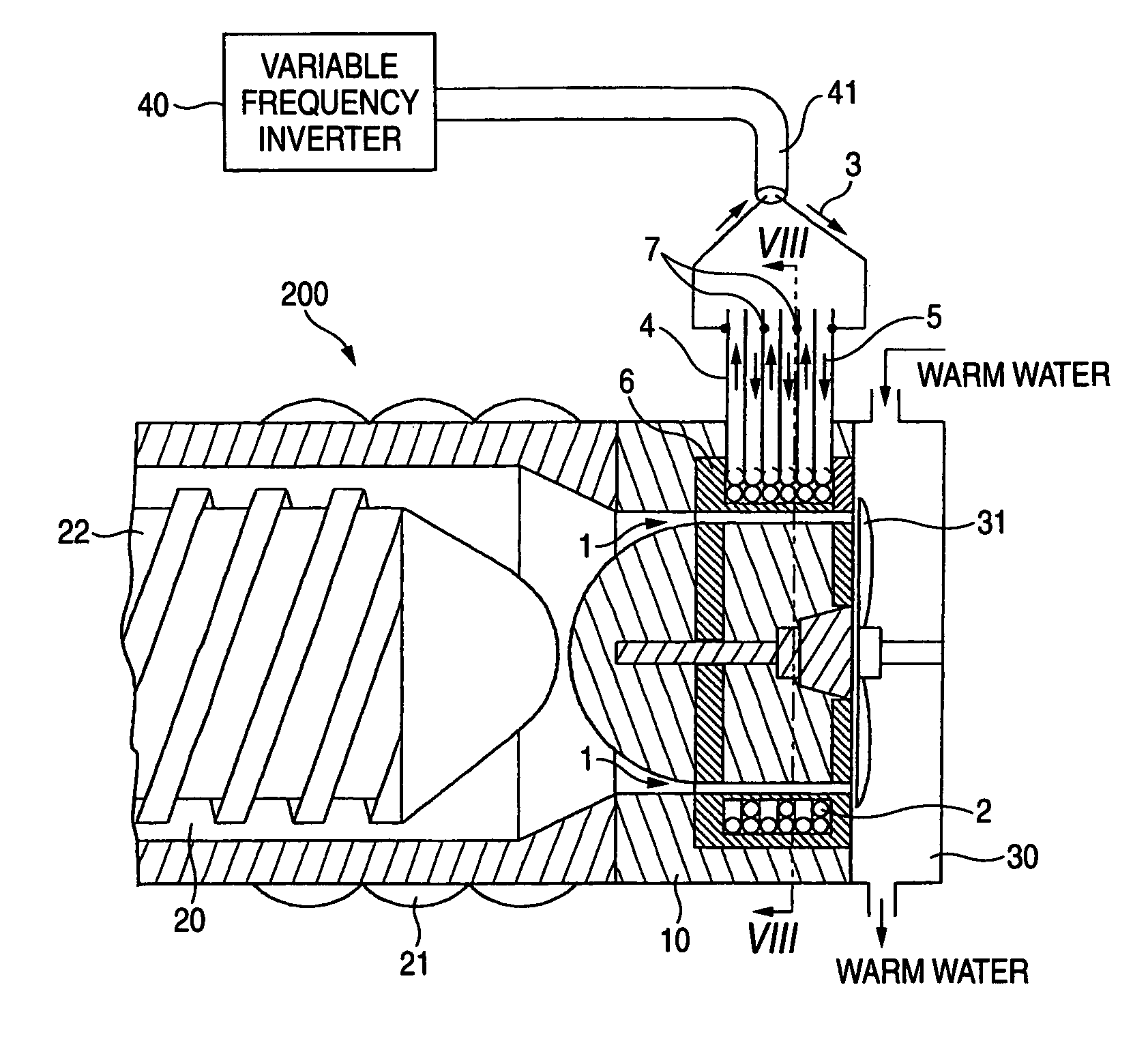
[0067]FIG. 7 is a longitudinal sectional view of the plastic extruder according to the third embodiment of this invention. FIG. 8 is a cross sectional view taken in line VIII-VIII in FIG. 7.
[0068] Around the nozzles 1 of the plastic die 10, a coil 2 accommodated in the coil case 6 is provided.
[0069] The coil 2 is an arrangement of coil units (8 in FIGS. 9A and 9B) each made by winding the conductive tube 4.
[0070] As seen from FIG. 7, the high frequency current 3 is supplied in series from the variable frequency inverter 40 to all the coil units 8 through the power supplying cable 41.
[0071] As seen from FIG. 8, the coolant 5 is supplied from the coolant pump 9a to the coolant supplying mouth 5a and passed in parallel each of the coil units 8. After the coolant 5 has cooled the coil 2, it returns to a coolant pump 9a via a radiator 9b from the coolant discharge mouth 5b.
[0072]FIG. 9A is a side view of a single coil unit 8, and FIG. 9B is a front view of the single coil unit 8.
[0...
PUM
| Property | Measurement | Unit |
|---|---|---|
| Frequency | aaaaa | aaaaa |
Abstract
Description
Claims
Application Information
 - R&D
- Intellectual Property
- Life Sciences
- Materials
- Tech Scout
- Unparalleled Data Quality
- Higher Quality Content
- 60% Fewer Hallucinations
Browse by: Latest US Patents, China's latest patents, Technical Efficacy Thesaurus, Application Domain, Technology Topic, Popular Technical Reports.
© 2025 PatSnap. All rights reserved.Legal|Privacy policy|Modern Slavery Act Transparency Statement|Sitemap|About US| Contact US: help@patsnap.com


