
High speed positive-working photothermographic radiographic film

a radiographic film and positive-working technology, applied in the direction of diffusion transfer process, instruments, photosensitive materials, etc., can solve the problems of image noise, undevelopable grains, image noise, etc., and achieve excellent thermal and light stability, high speed and discrimination, and high speed

Inactive Publication Date: 2005-11-03
CARESTREAM HEALTH INC
View PDF5 Cites 6 Cited by
  • Summary
  • Abstract
  • Description
  • Claims
  • Application Information

AI Technical Summary

Benefits of technology

[0027] In another embodiment, the photothermographic element comprises in part an internal phosphor, that is internal to, and integral with, the photothermographic element. The internal phosphor performs the same function as the external phosphor screen but it is coated within the photothermographic element. The internal phosphor may occupy the same layer as the silver halide emulsion or can be in a nearby layer of the photothermographic element. An internal phosphor may preclude the need for an external phosphor screen. In a preferred embodiment, one or more couplers or the like is present in the photothermographic element to accelerate development by removing Dox as it is formed, in order to drive development to Dmax.
[0030] The present invention has the advantage of high speeds. In fact, the above-mentioned second-stage positive image, taken to full development in the unexposed areas, can be at least two stops faster than the first-stage negative image. Thus, the inventive method and accompanying photothermographic element can form a positive image of high speed and discrimination when exposed and heated 10 to 40 sec at 150 to 185° C. Images have excellent thermal and light stability. Dmins (minimum densities) are stable after extended incubation to heat or light. These and other advantages will be apparent from the detailed description below.

Problems solved by technology

An exposure destroys preformed surface fog centers rendering the grains undevelopable.
If phosphors or metal oxides are included within the typical silver halide emulsion, image noise levels may increase.
This is due to the fact that electrons or visible radiation from the converting materials may expose silver halide grains outside of the image area, giving rise to image noise.
A significant problem with photothermographic elements has been the difficulty obtaining high photographic speeds.
Silver-halide emulsions that are optimally sensitized for photographic speed in aqueous gelatin generally lose speed in contact with organic solvents and non-gelatin binders that are used in many non-aqueous photothermographic systems.
Organic solvents may induce dye desorption, dye deaggregation, or some other chemical effect that degrades photographic efficiency.
Methods of chemical and spectral sensitizations in organic solvents are less effective than in water for similar reasons.
Gelatin coatings, on the other hand, are more difficult to thermally develop due to the physical properties of the gelatin when it is heated.
Gelatin coatings also require dispersing the incorporated water-insoluble developer components, which causes them to react generally more sluggishly under thermal processing conditions compared to organic solvent coatings in which developer components are dissolved in the coating solvent.

Method used


Image

  • High speed positive-working photothermographic radiographic film
  • High speed positive-working photothermographic radiographic film
  • High speed positive-working photothermographic radiographic film

Examples


example 1

[0217] The following aqueous multilayer coating, in Table 2, was prepared using negative-working emulsion E-2 according to methods known in the art. The support was 0.018 cm (0.007 inch) thick poly(ethylene terephthalate).

TABLE 2Componentg / m2Layer 1: InterlayerGelatinEthene, 1,1′-0.14(methylenebis(sulfonyl))bis-Layer 2: Imaging LayerPan-Sensitive Silver (from.54emulsion E-2)Silver (from silver salt SS-1)1.08Silver (from silver salt SS-2)1.08Phenolic Coupler PC-4 (from1.08PCD-5)Developer D-17 (from DD-1)1.08Salicylanilide (from TSD-1)2.16Gelatin6.88Layer 3: OvercoatGelatin3.23Surfactant SF-10.01Ludox ® AM (colloidal silica)0.15

example 2

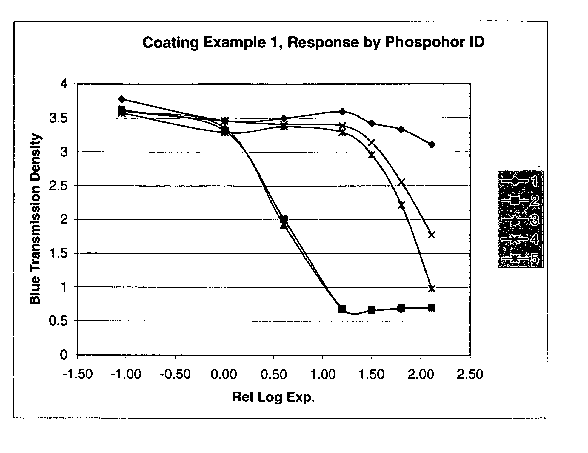
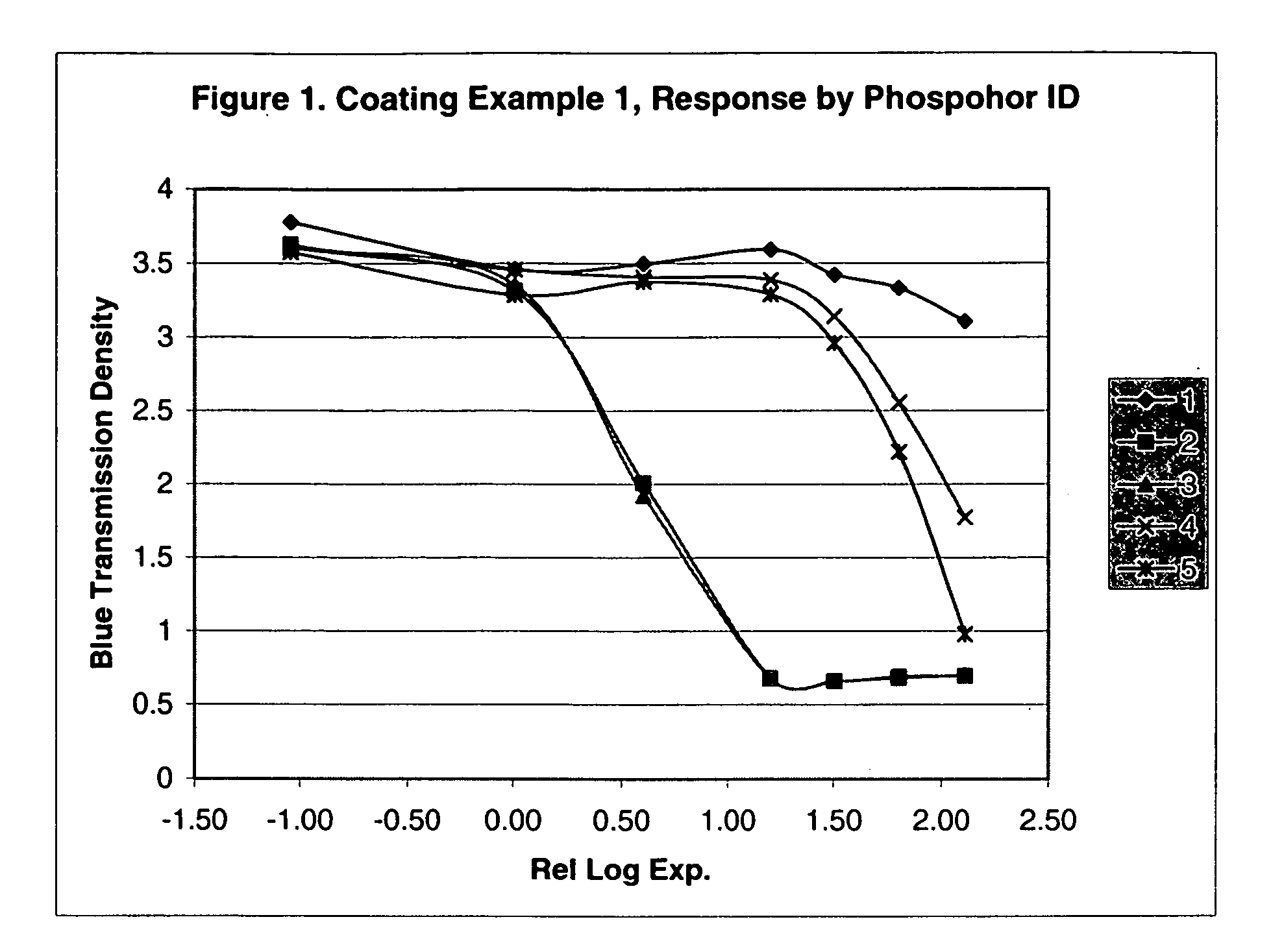
[0218] Example 2 illustrates the sensitivity of coating Example 1 when combined with several phosphor intensifying screens. Coating Example 1 was placed in face-side contact with each screen and the combined film packet was exposed to x-ray radiation with the backside of the intensifying screen facing the x-ray source. The x-ray exposures ranged from 0.09 mRems to 128.8 mRems. Table 3 below lists the peak wavelength emitted by each screen, Table 4 shows the x-ray source settings for each exposure level, and Table 5 lists, for each exposure level, the developed blue transmission density after thermally processing coating Example 1 at 162° C. for 30 sec. FIG. 1 shows the H & D photographic curve (developed blue transmission density vs relative log exposure level) which has a decreasing slope indicating a positive response (decreasing density with increasing exposure).

TABLE 3Phosphor ID12345DescriptionLaPO4:CeXOMATICDupontLaPO4:Gd2O2S:REGHI PLUSCe, TbEuCoverage60 g / m{circumflex over ...

example 3

[0222] The following aqueous single layer coating shown in Table 6 was prepared using negative working emulsion E-1 and silver salt SS-3. The support was 0.018 cm (0.007 inch) thick poly(ethylene terephthalate).

TABLE 6Componentg / m2Layer 1: Imaging LayerGreen Sensitive Silver (from emulsion E-1)0.46Silver (from silver salt SS-3)0.46Phenolic Coupler PC-4 (from PCD-3)1.12Developer D-17 (from DD-1)0.34Salicylanilide (from TSD-1)0.86Gelatin3.77


PUM

PropertyMeasurementUnit
light wavelengthsaaaaaaaaaa
temperatureaaaaaaaaaa
temperaturesaaaaaaaaaa

Abstract

The present invention is directed to a method of forming a positive image in a photothermographic assembly comprising a photothermographic material and an intensifying means for converting ionizing radiation, wherein the assembly has been imagewise exposed to ionizing radiation to form a latent image in the photothermographic material. The photothermographic material has at least one imaging layer comprising a potentially negative-working emulsion, wherein thermal development of unexposed silver salts in exposed areas relative to unexposed areas is inhibiting when thermally developing the imagewise exposed assembly, thereby producing a positive image. The present invention is also directed to a photothermographic assembly that can be used in the present process in which a positive image characterized by high speed and discrimination is formed when exposed and thermally heated above 150° C.

Description

FIELD OF THE INVENTION [0001] This invention relates to a high-speed positive-working silver-halide photothermographic element for medical and industrial radiography, and a process of making an image employing such element. BACKGROUND OF THE INVENTION [0002] In conventional radiography, films containing light-sensitive silver-halide grains are employed in a number of image recording devices including but not limited to x-ray imaging cassettes, film based dosimeters and intra-oral dental film packets. Upon exposure, the film produces a latent image that is only revealed after suitable processing. These film elements have historically been processed by treating the exposed film with at least a developing solution having a developing agent that acts to form an image in cooperation with other components in the film. [0003] It is always desirable to limit the amount of solvent or processing chemicals used in the processing of silver-halide films. The traditional photographic processing s...

Claims


Application Information

Patent Timeline
Patent Type & Authority Applications(United States)
IPC IPC(8): G03C1/498G03C3/00G03C5/17G03C8/00
CPCG03C1/49818G03C1/49881G03C3/003G03C5/17G03C1/0051G03C2200/43
Inventor ROBERTS, MICHAEL R.SIEBER, KURT D.GILMAN, PAUL B. JR.
Owner CARESTREAM HEALTH INC
Learn More