Apparatus and method for handling interdevice signaling

a technology of inter-device communication and apparatus, applied in logic circuits, oscillator generators, pulse techniques, etc., can solve the problems of limiting the speed of communication that can be achieved, slowed down the entire system, and general limitation of inter-chip high-speed communication. achieve the effect of improving signaling speed

Active Publication Date: 2005-11-03
TEXAS INSTR INC
View PDF11 Cites 2 Cited by
  • Summary
  • Abstract
  • Description
  • Claims
  • Application Information

AI Technical Summary

Benefits of technology

[0008] It is, therefore, an object of the present invention to provide an apparatus and method for handling interdevice signaling between a sending device and a receiving device that improves signaling speed between the sending device and the receiving device.

Problems solved by technology

Inter-chip high speed communication is generally limited by the performance of chip communication termination circuits, such as driver and receiver circuits at the interface of communicating chips.
Inherent driver circuit limitations often limit speed of communication that can be achieved by a system.
Chip-to-chip communication (i.e., inter-chip communication) often presents bottlenecks in certain aspects of design of a system, such as communications with motherboards, optical transmission links, intelligent network hubs, routers and other system components.
If one of the inter-chip interfaces experiences slow communications, then the entire system is slowed.
The problem with such an approach is that application of the remedial boosting signal necessarily occurs too late to aid in speeding the transition of the output signal that is sensed.

Method used


Image

  • Apparatus and method for handling interdevice signaling
  • Apparatus and method for handling interdevice signaling
  • Apparatus and method for handling interdevice signaling

Examples


Embodiment Construction

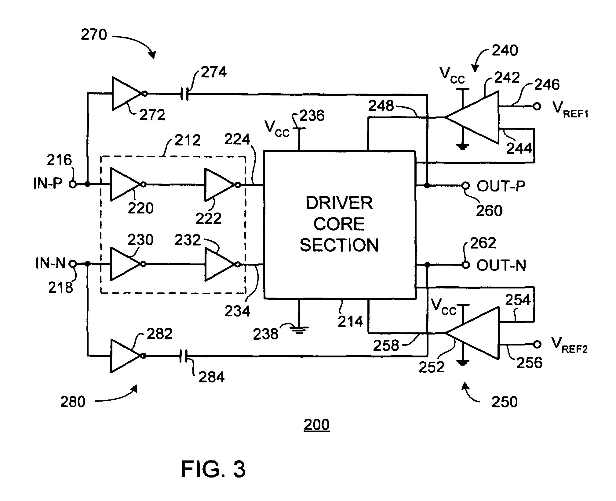
[0016]FIG. 1 is an electrical schematic diagram of a representative prior art driver apparatus. In FIG. 1, a driver apparatus 10 includes an input section or locus 12 and a driver core section 14. Driver apparatus 10 is configured, by way of example and not by way of limitation, as a differential signaling driver receiving a first input signal IN-P at a first input terminal 16 and receiving a second input signal at a second input terminal 18. In representative driver circuit 10, input section 12 includes a pair of inverters 20, 22 coupled in series between first input terminal or locus 16 and a first core input terminal 24. Input section 12 also includes a pair of inverters 30, 32 coupled in series between second input terminal or locus 18 and a second core input terminal 34. Driver core section 14 receives a supply voltage VCC at a supply voltage input terminal 36. Driver core section 14 is coupled with ground 38.

[0017] A first regulating circuit 40 includes an amplifier 42 having...


PUM


Abstract

An apparatus for handling signaling between a sending device and a receiving device includes: (a) a buffering amplifier device having at least one input locus for receiving an input signal from the receiving device and having at least one output locus for presenting an output signal for the receiving device; each respective at least one output locus presents an output signal in response to the input signal received at a respective input locus of the at least one input locus; (b) a feed forward circuit coupling each respective input locus with its respective corresponding output locus to provide a feed forward signal to the respective corresponding output locus; the feed forward signal is in phase with the input signal received at the respective input locus.

Description

BACKGROUND OF THE INVENTION [0001] The present invention is directed to driver apparatuses employed in inter-device communications signaling, and especially to such driver apparatuses employed in high speed communication systems. [0002] In high speed communications systems such as, by way of example and not by way of limitation, data communication systems, speed of signal handling is less of a problem when effecting intra-chip communications than when carrying out inter-chip communications. Inter-chip high speed communication is generally limited by the performance of chip communication termination circuits, such as driver and receiver circuits at the interface of communicating chips. Speed of a driver circuit is generally indicated by the speed at which the driver circuit can effect signal transitions. Signal transitions—such as from a high signal level to a low signal level, or from a low signal level to a high signal level—are used in digital data communications to convey informa...

Claims


Application Information

Patent Timeline
Patent Type & Authority Applications(United States)
IPC IPC(8): H03B1/00H03K19/017
CPCH03K19/01707
Inventor CARVAJAL, FERNANDO D.FAN, YANLI
Owner TEXAS INSTR INC
Why Eureka
Try Eureka