Engine systems and methods

a technology of hypersonic compression waves and engine systems, which is applied in the direction of machines/engines, rocket engine plants, and intermittent jet plants, etc., can solve the problems of limited construction material strength, high internal pressure of combustion in both jet and rocket engines, and the inability to realize the full potential of the machine industry. , to achieve the effect of minimal inertial loss

Inactive Publication Date: 2005-10-27
DUNCAN RONNIE J
View PDF6 Cites 14 Cited by
  • Summary
  • Abstract
  • Description
  • Claims
  • Application Information

AI Technical Summary

Benefits of technology

[0038] In accordance with further aspects of the invention, a directed thrust is formed in a pulsed manner using a contained burn that starts at a peripheral base area and is directed in a tapered-conical shape that forms a primary compression area adjacent the apex of the conical shape. The compressed burn thereafter continues to the apex of the tapered-conical shape, creating a high-speed convergence or secondary compression zone before being exhausted. This construction provides a more complete ignition within the chamber, enhancing efficiency by capturing more of the energy before it leaves the engine. It also allows for the combustion products to exit the primary combustion chamber more rapidly, thus allowing a higher pulse rate of firing while maintaining the high compression exhaust flows by not compressing exhaust products to final velocity internally.
[0079] In accordance with yet other aspects of the invention, the combustion and expansion chambers are shaped to allow efficient expansion of combustion products with minimal inertial loss.

Problems solved by technology

The full potential of the machine industry has yet to be realized in part because of several deficiencies in functionality, features, performance, reliability, cost-effectiveness, and convenience of existing systems.
Several problems are inherent in the conventional systems.
The combustion in both jet and rocket engines must contain extremely high internal pressures and are therefore limited by construction material strength.
As the internal combustion pressure increases, the combustion chamber wall must increase in thickness to contain the pressure, increasing the combustion chamber weight proportionally and limiting the design.
Also, as the exhaust nozzle diameter is reduced to increase exhaust speed, cooling the engine and nozzle becomes increasingly more difficult.
In addition, pulsed engines are unable to evacuate the combustion products in a short time moment, thus limiting the firing speed.
Furthermore, as internal pressure in the combustion chamber increases, higher fuel and oxidizer inlet pressures are required to introduce fuel and oxidizer into the combustion chamber, requiring heavier weight pumps that operate at higher horsepower.
The huge plume of fire trailing the shuttle and other rockets is caused by incomplete combustion of the fuel and oxidizer prior to exiting the exhaust nozzle.
The fuel and oxidizer igniting outside the engine provide virtually no thrust and are thus wasted.
Furthermore, the continuous ignition of present engines causes high heat transfer to engine parts, particularly the nozzle orifice, and the high heat transfer requires the use of costly exotic materials and intricate cooling schemes to preserve the engine structure.
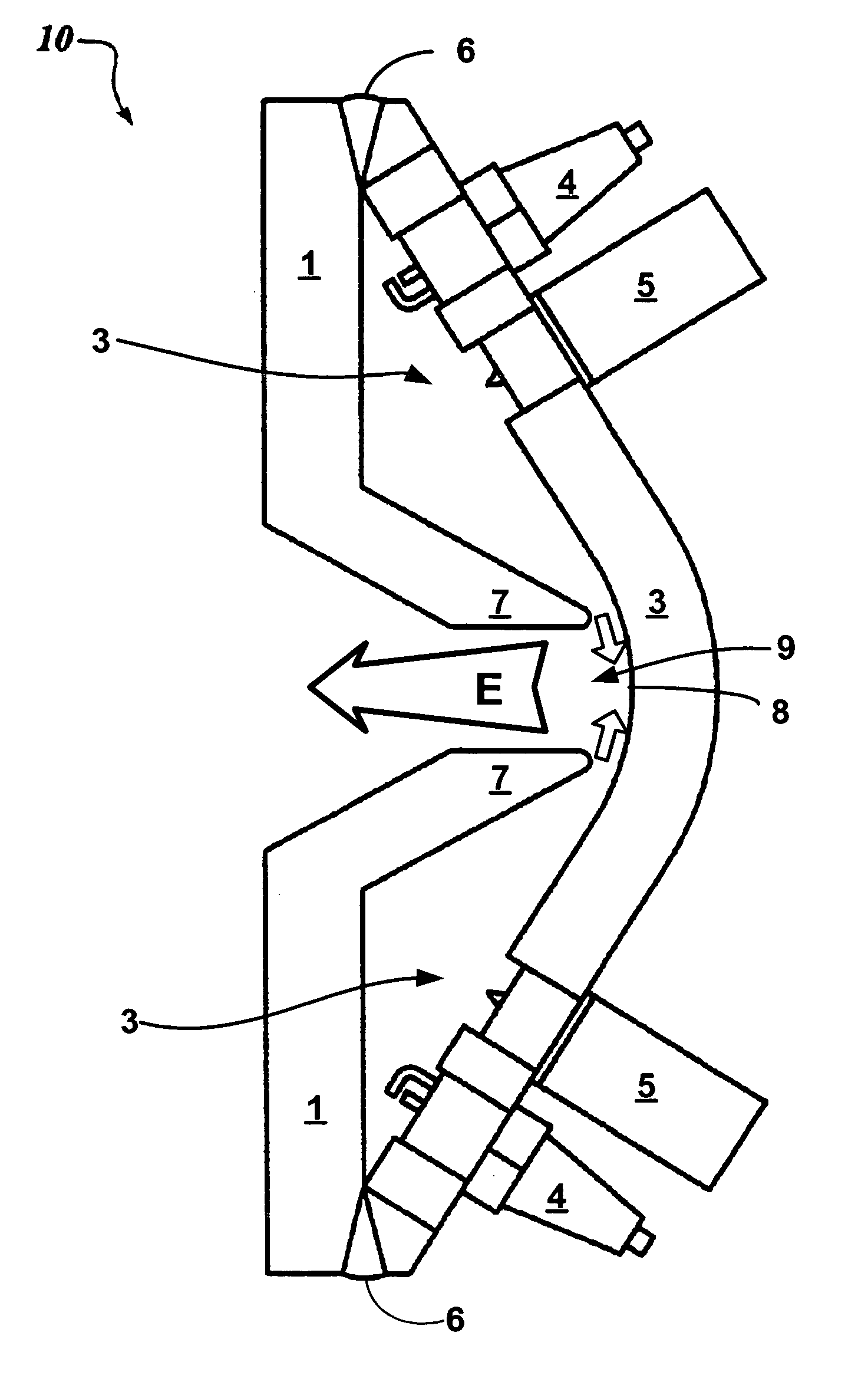
While the prior art addresses many aspects of propulsion devices, it does not teach the use of a shaped charge in a jet or rocket engine.
While the general theory behind shaped charges has been known for many years, the prior art has restricted the use of shaped charges to warheads and certain other expendable detonation devices.
Examples of shaped charge devices are described in U.S. Pat. No. 5,275,355 to Grosswendt, et al., entitled “Antitank Weapon For Combating a Tank From The Top,” and U.S. Pat. No. 5,363,766 to Brandon, et al., entitled, “Ramjet Powered, Armor Piercing, High Explosive Projectile.” Shaped charges in such devices are not used to provide propulsion.
However improved in power efficiency, the use of aerosolized oil-in-gas premixed fuels comes at the expense of increased hydrocarbon (HC), Nitrogen Oxides (NOx), and carbon monoxide (CO) pollutant emissions due to the greater difficulty in combusting the lubricating oil pre-mixed in the gasoline.
Furthermore, two-cycle engines are fuel inefficient because a portion of the incoming air-fuel charge is used to displace the exhaust is unavoidably short circuited to the exhaust port.
However, despite its widespread use, the internal combustion, or Otto cycle, engine or, in certain instances, a diesel cycle engine, has received very little technological advancement.
The reciprocating motion of common internal combustion engines, Otto and diesel cycle, is an inefficient method of producing rotary power.
The reciprocating motion of the four-cylinder engine requires four inertial changes of the rotating mass of the pistons, connecting rods, and assembly—each change in inertia yielding a power loss to the system.
Likewise, each complete cycle of the internal combustion engine requires four inertial changes for the associated valves, springs, lifters, rocker arms, and push rods, yielding additional total loss of the engine.
The mechanical complexity of the standard internal combustion engine adds to the design's overall inefficiency.
Each one of these parts increases the probability of engine failure due to fatigue or wear.
Likewise, this large number of parts increases the amount of inertial mass that must change four times per cycle, reducing power produced by the system.
Each moving part is subject to frictional loss between each relative part, adding to power loss.
Further, it is expensive to manufacture and maintain equipment requiring such a large number of moving parts.
The resulting structural requirements limit piston assembly design, increasing mass and limiting material choice.
Further, transmissions are necessary to amplify the relatively low torque generated by the reciprocating motion, thus adding weight, cost, complexity and additional power requirements to the overall system.
The compression, and thus heating, of the original unit volume of combustion products leads to further power loss.
Likewise, the reciprocating design limits the combustion product's ability to do useful work because the expansion volume is not equal to the compression volume—combustion heats the gas, thus increasing the expansion volume beyond the initial volume.
Thus, relatively high-pressure combustion gases are exhausted without performing any useful work.
The overall design of Otto, diesel, and other rotary engines is limited by cross-leakage at high pressure.
More specifically, cross leaking is internal pressure loss due to overflow from the high-pressure side to the low-pressure side of the system while the pistons move throughout their stroke.
The excessive number of seals and connecting parts in other internal combustion engines creates cross-leakage liability.
Yet, another limitation of current rotary engine technology is the internal combustion design of the engines.
The current designs fail to allow for use as external combustion or external detonation cycle engines.
A further limitation of current engine technology is a lack of design diversity.
The extent of diversity for typical internal engines is limited by a need to drive a common crankshaft from a plurality of reciprocating motions.
This limited design diversity prevents possible space-saving designs from being developed.
Another design limitation of the internal combustion engine is the singularity of its use.
Furthermore, the internal combustion engine itself is incapable of functioning as an air compressor, a vacuum pump, an external combustion engine, water pump, a drive turbine for expandable gas, or a drive turbine.
However, current methods to produce hydrogen use fossil fuels and high temperatures to produce the hydrogen.
Furthermore, these methods produce carbon dioxide and NOx, thus negating any environmental advantages.
Biological processes to produce hydrogen are intriguing, but considerable technical challenges still exist.
A major challenge is to have high rates of hydrogen production and still use an inexpensive energy source for the biological production.
Photosynthetic methods can employ solar radiation, but the hydrogen production is too slow to be of use.
Fermentation methods can produce hydrogen at high rates, but require expensive energy sources such as glucose.
Biomass would seem to be ideal as source of glucose, however, the problem with biological hydrogen production is the same as with biological ethanol production from biomass: inefficient degradation of the cellulosic material containing the glucose.

Method used


Image

  • Engine systems and methods
  • Engine systems and methods
  • Engine systems and methods

Examples


Embodiment Construction

[0112] General Construction of the Shaped Charge Engine. FIG. 1 schematically illustrates in cross-section a device constructed in accordance with the present invention for dynamically compressing and detonating a combustible mixture to form a shaped compression wave. Reference numeral 10 generally refers to a shaped charge engine. The engine 10 includes a hollow blast-forming chamber 3 formed between an outer charge forming housing 2 and an inner charge forming housing 1. The outer charge forming housing 2 is generally round-conical in shape and includes a centrally located dome shaped portion at the apex to form a concave “cup” or “bowl” shape.

[0113] The inner charge forming housing 1 comprises a generally flat plane transitioning to a centrally located generally conical-shaped projection 7. The projection 7 extends radially inward and upward toward the outer housing 2. The projection 7 is truncated below the tip to form a centrally located generally circular opening at the small...


PUM


Abstract

The present invention relates generally or preferably to pulsed hypersonic compression waves and more particularly to shaped charge devices using pulsed hypersonic compression waves to create thrust, two-cycle internal and external combustion engines, rotary machines and more specifically to internal and external rotary combustion engines, fluid compressors, vacuum pumps, and drive turbines for expandable gases or pressurized fluid and water, as well as hydrogen.

Description

PRIORITY CLAIM [0001] This application is a continuation-in-part of and claims priority to U.S. patent application Ser. No. 10 / 172,406 filed Jun. 14, 2002 which claims priority to and is a continuation of U.S. patent application Ser. No. 09 / 517,130 filed Mar. 2, 2000, now U.S. Pat. No. 6,430,919. [0002] This application also claims priority to and is a continuation-in-part of U.S. patent application Ser. No. 10 / 261,097 filed Sep. 30, 2002, a divisional of application Ser. No. 09 / 850,937 filed May 7, 2001. [0003] This application claims priority to and is a continuation-in-part of U.S. patent application Ser. No. 10 / 261,102 filed Sep. 30, 2002, a divisional of application Ser. No. 09 / 850,937 filed May 7, 2001. [0004] This application is also a continuation-in-part of U.S. application Ser. No. 10 / 261,174 filed Sep. 30, 2002, which claims priority to and is a divisional of U.S. application Ser. No. 09 / 850,937 filed May 7, 2001 (U.S. Pat. No. 6,484,687 issued Nov. 26, 2002). [0005] Each...

Claims


Application Information

Patent Timeline
IPC IPC(8): F02B51/06F02K7/02F02K7/075F02K9/00
CPCF02B51/06F02K7/02Y02T10/126Y02T50/672F02K7/075Y02T10/12Y02T50/60
Inventor DUNCAN, RONNIE J.
Owner DUNCAN RONNIE J
Why Eureka
Try Eureka