
Method for reciprocating a workpiece through an ion beam

a technology of workpieces and ion beams, applied in the field of semiconductor processing systems, can solve the problems of reducing system flexibility, increasing system cost, and large size of ion implanters, and achieve the effect of generally minimizing the torque associated with the first axis

Active Publication Date: 2005-10-20
AXCELIS TECHNOLOGIES
View PDF19 Cites 9 Cited by
  • Summary
  • Abstract
  • Description
  • Claims
  • Application Information

AI Technical Summary

Benefits of technology

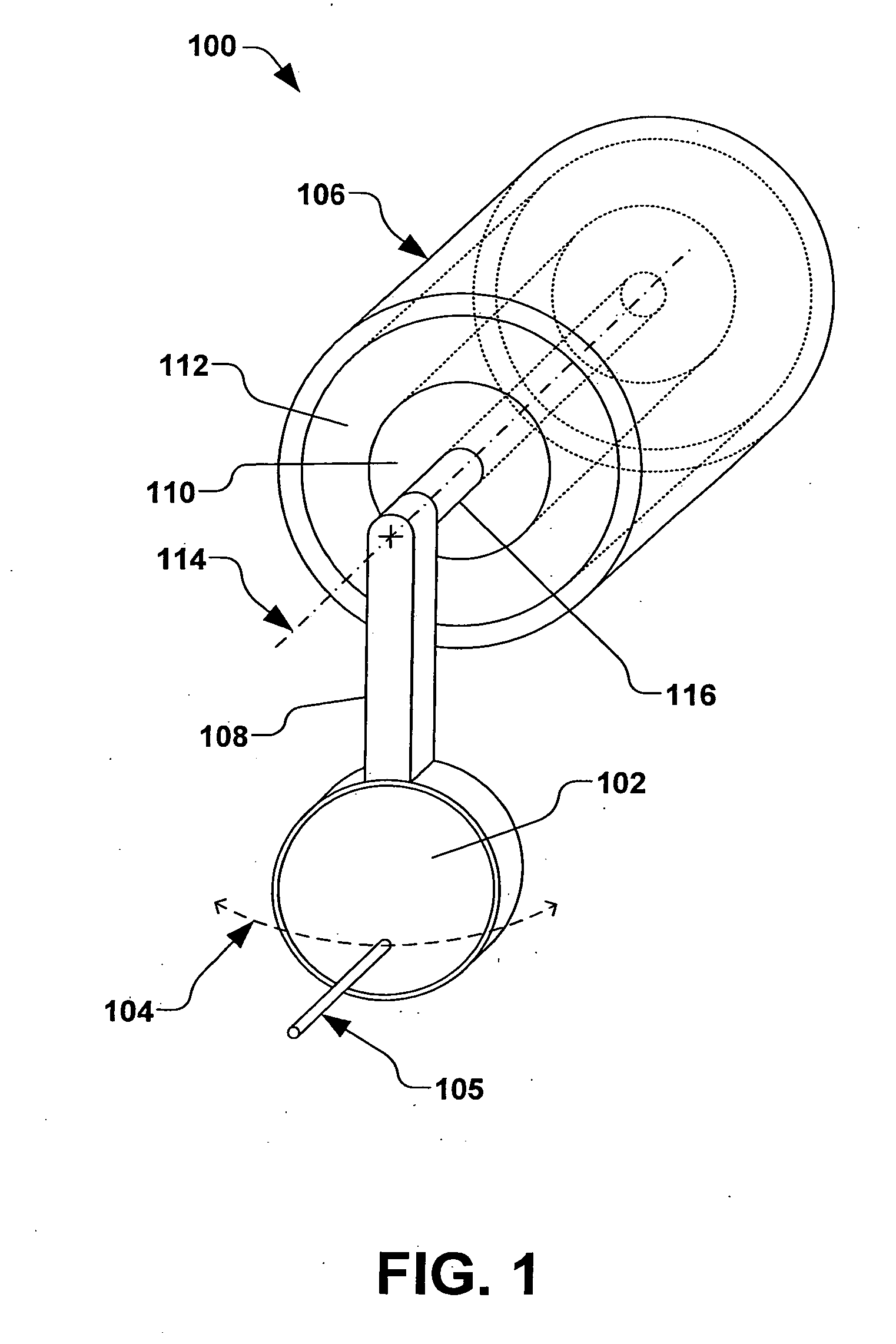
[0011] According to another exemplary aspect of the invention, an inertial mass is coupled to the stator, wherein the inertial mass rotates about the first axis and generally provides a reversal of direction of rotation of the scan arm, and thus, a reversal of direction of the workpiece along the first scan path. The inertial mass is further balanced about the first axis, wherein a torque in relation to the first axis is generally minimized. Therefore, the electromagnetic force between the rotor and the stator is operable to rotate the stator in reaction to an acceleration or deceleration of the rotor, thus generally confining inertial forces to the first axis.

Problems solved by technology

Processing batches of workpieces in such a manner, however, generally increases the cost of the system, makes the ion implanter substantially large in size, and reduces system flexibility.
The process of scanning or shaping a uniform ion beam, however, generally requires a complex beam-line, which is generally undesirable at low energies.
However, such a uniform translation and / or rotation can be difficult to achieve, due, at least in part, to substantial inertial forces associated with moving the conventional devices and scan mechanisms during processing.
This two-dimensional scanning apparatus, however, utilizes direct drive actuators to linearly translate the wafer in the fast scan direction, wherein the transport velocity of the wafer in the fast scan direction is substantially limited due, at least in part, to significant inertial forces encountered during acceleration and deceleration of the wafer as the direction of fast scan transport is periodically reversed.
Large inertial forces in the conventional apparatus are accordingly associated with a large reaction force at the direct drive actuator, wherein the large reaction force can ultimately lead to significant vibration of the apparatus, thus having a deleterious impact on the ion implantation process.
Vibration may also pose a problem for nearby equipment, such as lithography equipment that is typically vulnerable to vibration.
Furthermore, when the speed of the translation in the fast scan direction is limited in order to avoid vibration issues, process throughput can be deleteriously impacted.

Method used


Image

  • Method for reciprocating a workpiece through an ion beam
  • Method for reciprocating a workpiece through an ion beam
  • Method for reciprocating a workpiece through an ion beam

Examples


Embodiment Construction

[0021] The present invention is directed generally towards a reciprocating drive system, apparatus, and method for reciprocally translating a workpiece in one or more dimensions. More particularly, the reciprocating drive apparatus is operable to translate the workpiece in two generally orthogonal dimensions along respective first and second scan paths with respect to an ion beam, wherein the workpiece may be translated at a generally constant translational or linear velocity when being subjected to the ion beam. Furthermore, as implied by the term “reciprocating drive apparatus”, the apparatus and method of the present invention provide a reciprocating and selectively reversible transport of the workpiece along the first scan path, and is advantageously operable to limit vibration and to optimize control of the reciprocating or oscillating transport motion of the workpiece along the first scan path. In particular, the reciprocating drive apparatus of the present invention comprises...


PUM


Abstract

A method for reciprocally transporting a workpiece on a scan arm through an ion beam is provided, wherein the scan arm is operably coupled to a motor comprising a rotor and stator that are individually rotatable about a first axis. An electromagnetic force applied between the rotor and stator rotates the rotor about the first axis and translates the workpiece through the ion beam along a first scan path. A position of the workpiece is sensed and the electromagnetic force between the rotor and stator is controlled in order to reverse the direction of motion of the workpiece along the first scan path, and wherein the control is based, at least in part, on the sensed position of the workpiece. The stator further rotates about the first axis in reaction to the rotation of the rotor, particularly in the reversal of direction of motion of the workpiece, thus acting as a reaction mass to the rotation of one or more of the rotor, scan arm, and workpiece.

Description

REFERENCE TO RELATED APPLICATION [0001] This application claims priority to and the benefit of U.S. Provisional Application Ser. No. 60 / 559,672 which was filed Apr. 5, 2004, entitled RECIPROCATING DRIVE SYSTEM AND METHOD and U.S. Provisional Application Ser. No. 60 / 569,338 which was filed May 7, 2004, entitled RECIPROCATING DRIVE SYSTEM AND METHOD, the entirety of which are hereby incorporated by reference as if fully set forth herein.FIELD OF THE INVENTION [0002] The present invention relates generally to semiconductor processing systems, and more specifically to a system, apparatus, and method for controlling reciprocating transport of a workpiece to provide precision scanning of the workpiece during semiconductor processing. BACKGROUND OF THE INVENTION [0003] In the semiconductor industry, various manufacturing processes are typically carried out on a workpiece (e.g., a semiconductor wafer) in order to achieve various results thereon. Processes such as ion implantation, for examp...

Claims


Application Information

Patent Timeline
Patent Type & Authority Applications(United States)
IPC IPC(8): A61N5/00B65H1/00H01J37/317H01L21/00H01L21/687
CPCH01J37/20H01J37/3171H01J2237/0216H01J2237/20228H01L21/68792H01J2237/31703H01L21/67069H01L21/67259H01L21/68764H01J2237/20292H01J37/317B65H1/00
Inventor VANDERPOT, JOHN W.POLLOCK, JOHN D.BERRIAN, DONALD W.
Owner AXCELIS TECHNOLOGIES
Learn More