
Apparatus, system, and method for high flux, compact compton x-ray source

Active Publication Date: 2005-10-13
LYRA ACQUISITION HLDG LLC
View PDF9 Cites 30 Cited by
  • Summary
  • Abstract
  • Description
  • Claims
  • Application Information

AI Technical Summary

Benefits of technology

[0016] One embodiment of an x-ray source generating x-rays from Compton backscattering includes: an electron storage ring for storing electron bunches, the electron storage ring guiding electrons in an orbit around the electron storage ring that passes through an interaction point disposed along a portion of the electron storage ring, electron bunches stored in the electron storage ring having at least one attribute related to the emission of x-rays that degrades after initial injection according to a time response; an injector for injecting electron bunches into the electron storage ring;

Problems solved by technology

The large physical size, high cost, and complexity of conventional synchrotrons have limited their applications.
For example, in many universities, hospitals, and research centers there are limitations on floor space, cost, power, and radiation levels that make a conventional synchrotron impractical as a local source of x-ray radiation.
As a result, there are many medical and industrial applications that have been developed using synchrotron radiation that are not widely used because of the unavailability of a practical local source of synchrotron radiation having the necessary x-ray intensity and spectral properties.
Conventional Compton x-ray sources have several drawbacks that have heretofore made them impractical in many applications.
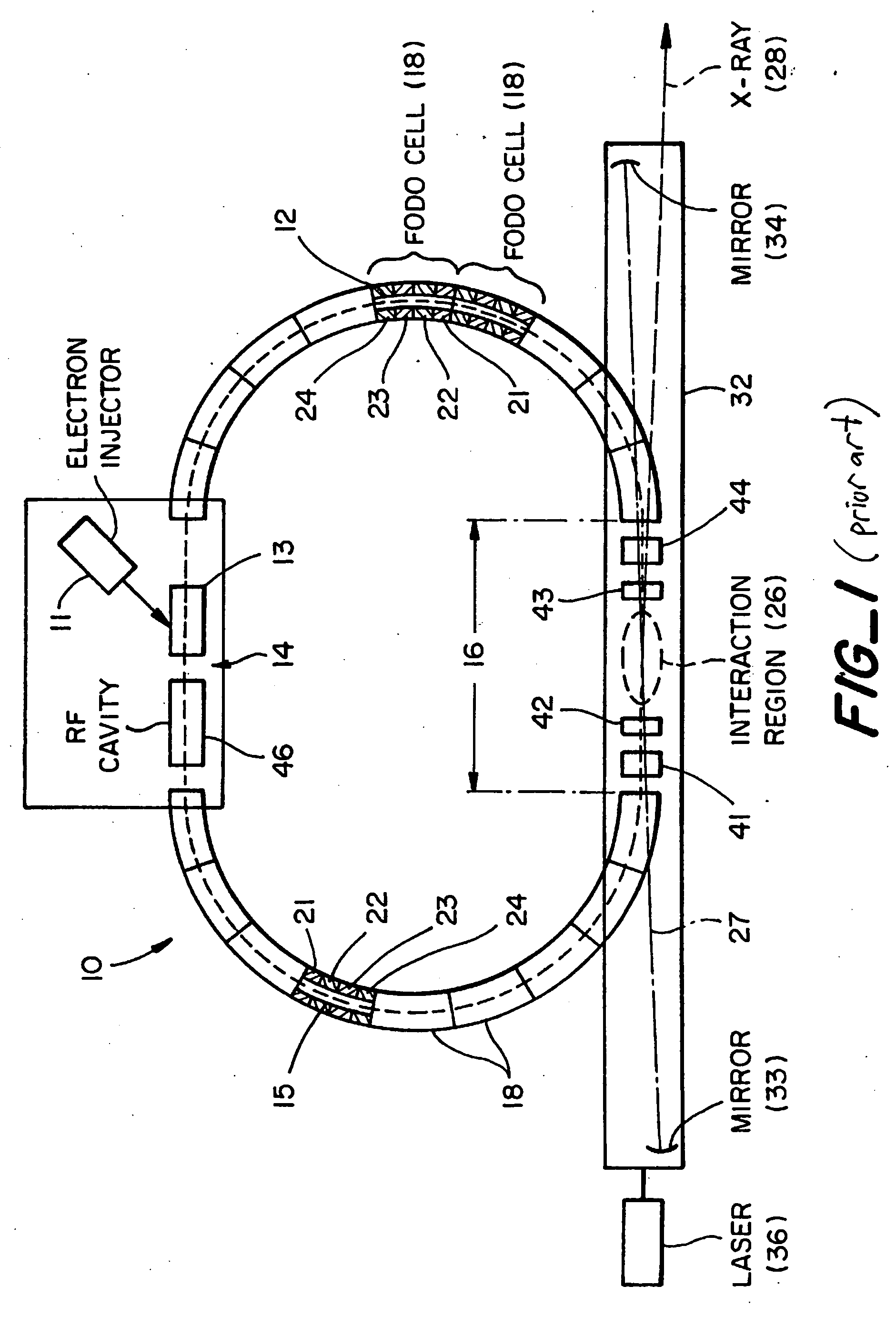
In particular, prior art compact Compton x-ray sources, such as that described in U.S. Pat. No. 6,035,015, are not sufficiently bright x-ray sources for narrowband applications, such as protein crystallography or phase contrast imaging.
The brightness is also less than desired because the optical power level that can be coupled into and stored in the Fabry-Perot cavity between mirrors 33 and 34 for use in Compton backscattering is less than desired, due to a number of limitations on the control, stability, and losses in different elements of the optics system.
Additionally, U.S. Pat. No. 6,035,015 has the optical mirror 34 offset from the path of the x-rays to reduce x-ray absorption, resulting in the optical beam being a few degrees off from a true 180 degree backscattering geometry, which significantly reduces Compton backscattering efficiency.

Method used


Image

  • Apparatus, system, and method for high flux, compact compton x-ray source
  • Apparatus, system, and method for high flux, compact compton x-ray source
  • Apparatus, system, and method for high flux, compact compton x-ray source

Examples


Embodiment Construction

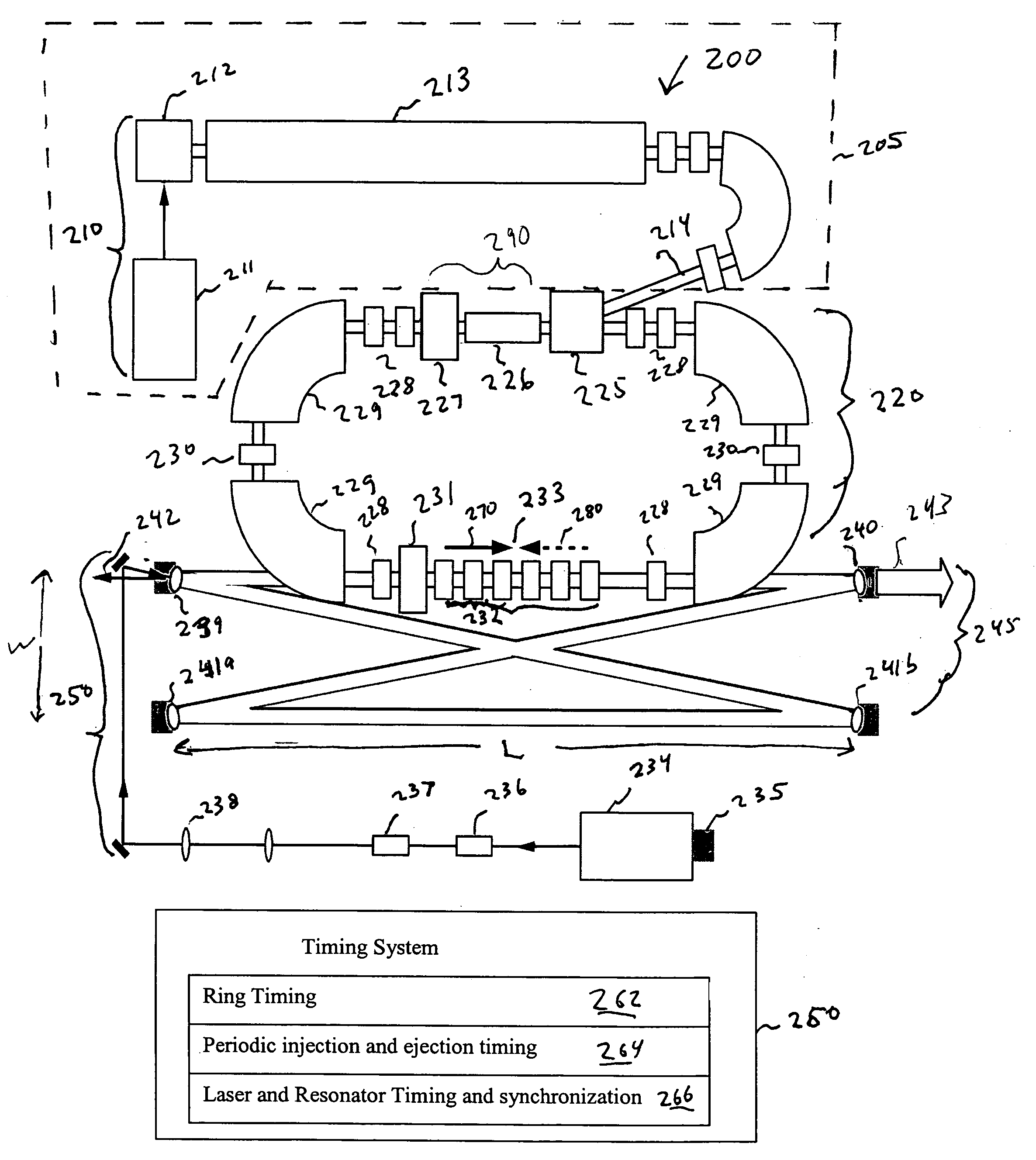
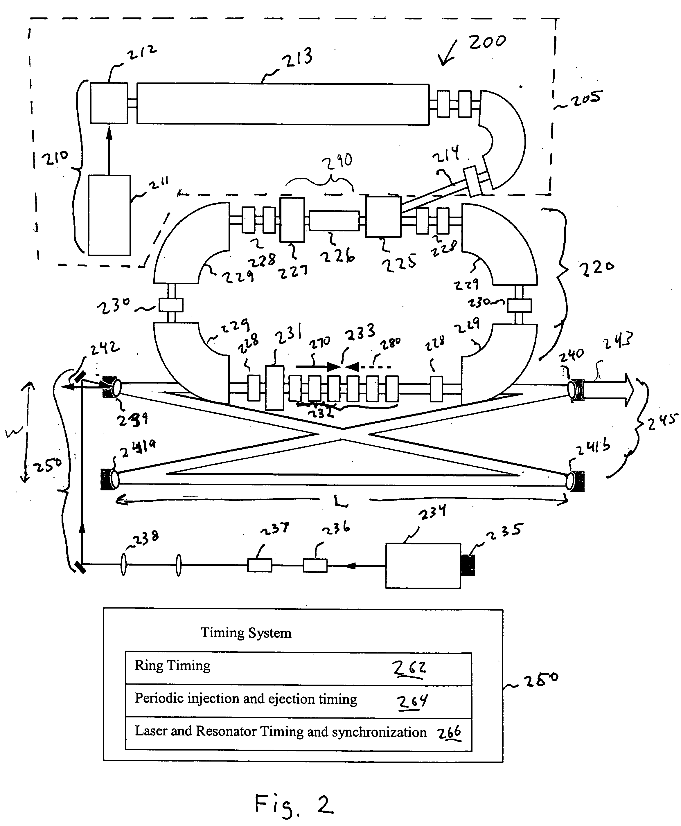
[0028]FIG. 2 illustrates a compact x-ray synchrotron source 200 having features facilitating the generation of nearly monochromatic, collimated, tunable, high-flux beam of x-rays suitable for many x-ray applications in accordance with one embodiment of the present invention.

[0029] X-ray synchrotron source 200 includes an injector 205 portion of the system having elements 211, 212, 213, and 214 for generating and injecting an electron bunch into an electron storage ring 220 via septum 225. An electron bunch is a group of electrons that, for example, has a spatial density envelope, energy and momentum distribution, and temporal pulse length. An electron source 210 produces an electron bunch using an RF gun 212 by striking a photocathode material, such as copper or magnesium, with a pulsed laser 211. A short linear accelerator section(s) 213 accelerates the electron beam to the full energy desired in the ring to obtain a desired x-ray energy for Compton scattering at approximately 180 ...


PUM


Abstract

A Compton backscattering x-ray source includes an electron storage ring for storing electron bunches. A timing system refreshes an orbiting electron bunch according to a schedule selected to improve at least one attribute of x-ray emission. In one implementation, the electron bunch is periodically refreshed with a period of at least about 10 Hz.

Description

CROSS REFERENCE TO RELATED APPLICATIONS [0001] This application claims the benefit of the following U.S. provisional patent applications: application Ser. No. 60 / 560,848 filed on Apr. 9, 2004, application Ser. No. 60 / 560,864, filed on Apr. 9, 2004; application Ser. No. 60 / 561,014, filed on Apr. 9, 2004; application Ser. No. 60 / 560,845, filed on Apr. 9, 2004; and application Ser. No. 60 / 560,849, filed on Apr. 9, 2004, the contents of each of which are hereby incorporated by reference.STATEMENT REGARDING FEDERALLY SPONSORED RESEARCH [0002] This invention was supported in part by a grant from the National Institutes of General Medical Sciences, National Institutes of Health, Department of Health and Human Services, grant number 4 R44 GM066511-02. The U.S. Government may have rights in this invention.BACKGROUND OF THE INVENTION [0003] Synchrotron x-ray radiation sources are of interest for many different fields of science and technology. A synchrotron x-ray radiation source has a wavele...

Claims


Application Information

Patent Timeline
IPC IPC(8): G01J1/00G01T1/24G21G4/00G21K1/06H01J35/00H01L25/00H01L27/00H01S3/00H01S3/13H05G2/00H05H1/00H05H7/06
CPCG02B5/10G21K1/02H05H7/06H05G2/00G21K1/06
Inventor RIFKIN, JEFFREYLOEWEN, RODERICK J.RUTH, RONALD D.
Owner LYRA ACQUISITION HLDG LLC
Learn More