
Electric motor having convex high-speed brush

a high-speed brush and electric motor technology, applied in the direction of dynamo-electric brake control, dynamo-electric brake/clutch, mechanical energy handling, etc., can solve the problems of motor speed increase, undesirable reduction of motor speed, undetectable differences, etc., and achieve the effect of faster high-speed outpu

Active Publication Date: 2005-10-06
TRICO PROD CORP
View PDF13 Cites 13 Cited by
  • Summary
  • Abstract
  • Description
  • Claims
  • Application Information

AI Technical Summary

Benefits of technology

[0013] Thus, the present invention overcomes the limitations of the prior art DC motors by providing a DC motor with an improved high-speed brush that does not have an initially slowed high-speed output during the brush wear-in period. Further, the present invention overcomes the limitations of the prior art DC motors by providing a DC motor with an improved high-speed brush that has an initially faster high-speed output so that it may be employed in a newly manufactured mechanical system to overcome any speed reduction caused by the stiffness of the new system. Finally, the present invention overcomes the limitations of the prior art DC motors by providing a DC motor with an improved high-speed brush that subsequently reduces its initially faster high-speed output so that it may be employed in a newly manufactured mechanical system to first, overcome any speed reduction caused by the stiffness of the new system, and to second, slow as the system loosens so that no apparent change in the system speed occurs.

Problems solved by technology

During the initial wear-in period of conventional two-speed DC motors, the seating of the brushes, and particularly the high-speed brush, causes the motor speed to increase.
This is somewhat noticeable when the motor is operating at low speed, but becomes undesirably distinct at the high speed setting.
However, a radial offset of the high-speed brush causes the brush to drag on the commutator and slow the armature during wear-in causing a like undesirable reduction in motor speed.
Furthermore, when running the two-speed DC motor in the high-speed mode, the initially slowed operation during the wear-in period may cause problems for the system it is employed in.
Conventional motor vehicle windshield wiper systems are mechanically complex with a number of rotating shafts, linkage arms, and pivot points.
All of the mechanical interaction between the parts of the wiper system and the gear reduction assembly of the DC motor, in addition to the slowed armature speed due to the high-speed brush wear-in cause the high-speed mode in many newly manufactured wiper systems to be nearly as slow as the low speed setting.
Eventually, the wiper system components loosen and the DC motor increases in speed as the break-in and wear-in periods complete.
However, this is an undesirably long process often requiring more than an hour of run time at the high-speed setting.
Furthermore, when the motor speed increases and the wiper system loosens, the resultant speed change in the high-speed setting may be excessively high.
For automotive manufacturers, this results in a high number of new car owner complaints regarding the high-speed operation of the wiper system.

Method used


Image

  • Electric motor having convex high-speed brush
  • Electric motor having convex high-speed brush
  • Electric motor having convex high-speed brush

Examples


Embodiment Construction

)

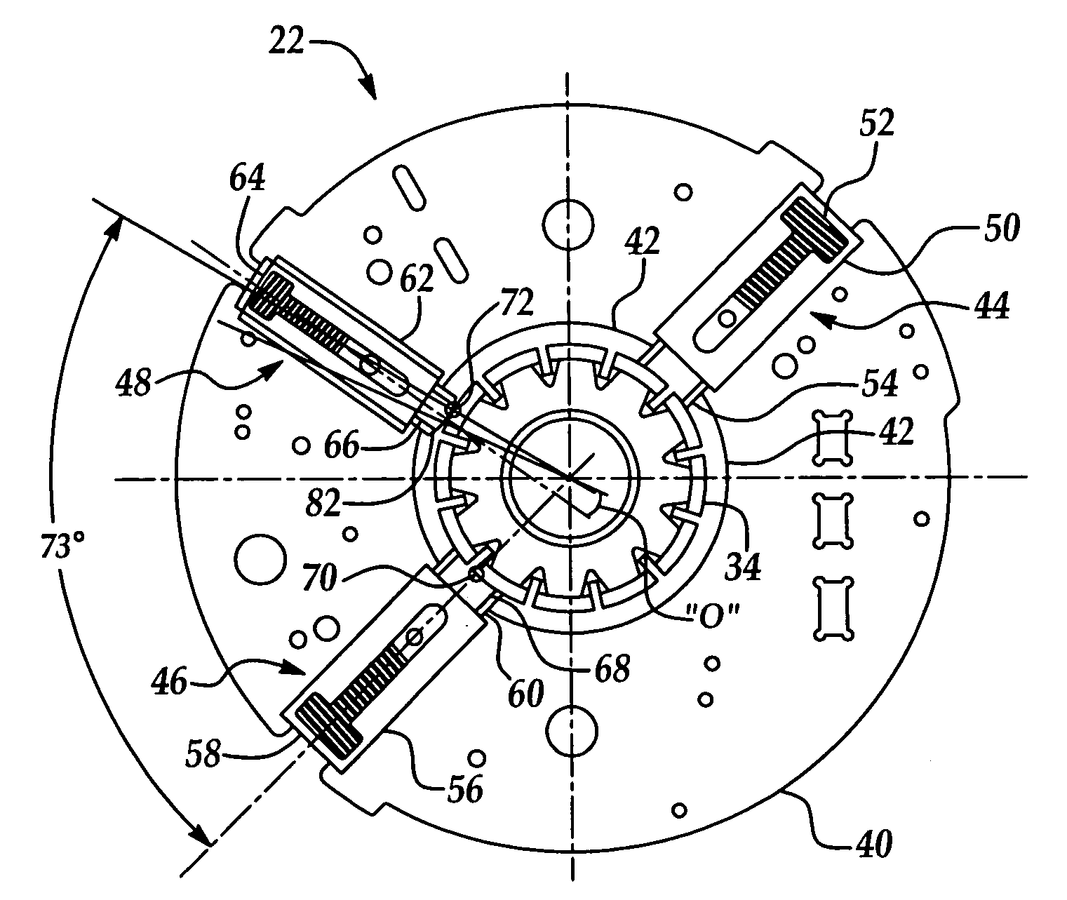
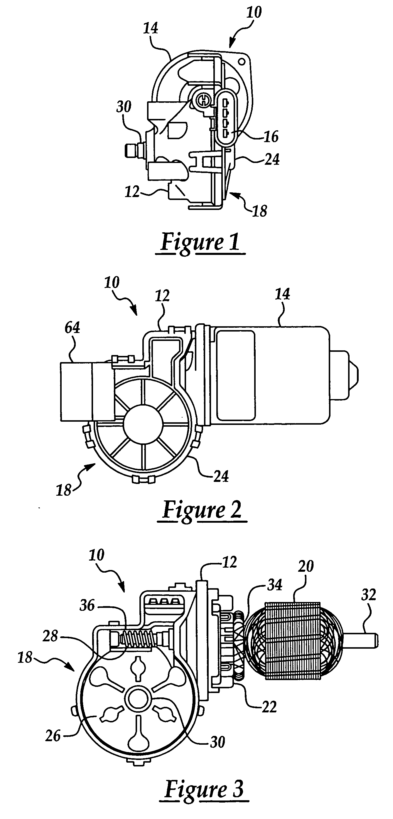
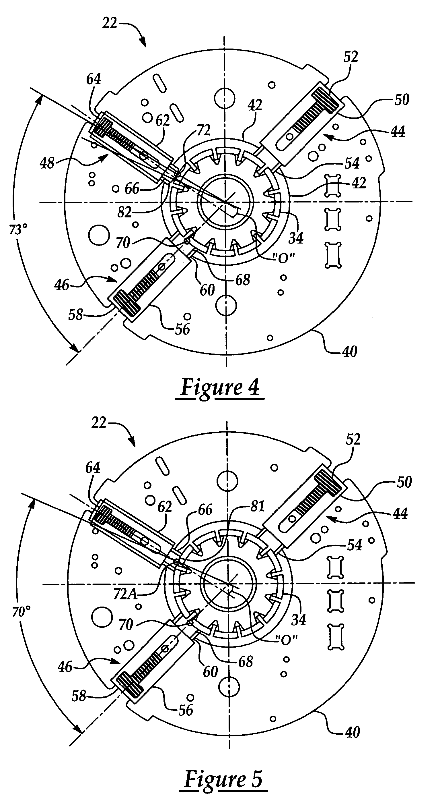
[0025] Referring now to the Figures, a two-speed DC motor of the present invention is generally indicated at 10 in FIGS. 1, 2, and 3 where like numerals are used to designate like structure. These Figures illustrate various views of the two-speed DC motor 10, which includes a main body 12, an armature case 14, and an electrical connector 16. The two-speed DC motor 10 illustrated herein is of a type that may be employed with a mechanical system that requires a stepped down motor output. Thus, as illustrated, the main body 12 may include a gear assembly generally indicated at 18, a wire wound armature 20, and a brush plate assembly 22. In FIG. 3, the cover plate 24 of the gear reduction assembly 18 and the armature case 14 are removed for clarity.

[0026] The gear reduction assembly 18 includes a drive wheel 26 that has teeth 28 formed about it outer circumference. A motor drive shaft 30 is fixedly mounted to the center of the drive wheel 26. The armature 20 includes a shaft 32 and co...


PUM


Abstract

A two speed direct current electric motor comprising: an armature having a commutator assembly that is adapted to receive an electromotive force to cause the armature to operatively rotate. A brush assembly having a common brush and a low-speed brush is disposed about and in electrical communication with the commutator to provide a first electromotive force to cause the armature to provide a low-speed rotational output. The brush assembly further includes a high-speed brush having a convex shaped end in physical and electrical communication with the commutator to provide a second electromotive force to cause the armature to provide a high-speed rotational output. The convex shaped end of the high-speed brush is further adapted to wear to take the shape of the commutator such that as the high-speed brush wears the high-speed rotational output decreases.

Description

[0001] This application claims priority to and all benefits from the co-pending provisional application having U.S. Ser. No. 60 / 557,471 filed Mar. 30, 2004 and entitled Electric Motor Having Convex High Speed Brush.BACKGROUND OF THE INVENTION [0002] 1. Field of the Invention [0003] The present invention relates, generally to two-speed electric motors and, more specifically, to a two-speed electric motor having a convex shaped high-speed brush. [0004] 2. Description of the Related Art [0005] Direct current (DC) motors are common and used in a wide variety of applications as a source of motive power. DC motors operate by causing an armature to rotate in a magnetic field to produce torque. In one form of DC motor, a magnetic field is developed within the motor case surrounding an armature that consists of a series of wire wound coils, or windings. Each end of each of the armature windings is electrically connected to one segment of a commutator. The commutator is a series of electrical...

Claims


Application Information

Patent Timeline
Patent Type & Authority Applications(United States)
IPC IPC(8): H01R39/41H02K13/00H02K23/20
CPCH02K23/20H01R39/41
Inventor SUMINSKI, DAVID
Owner TRICO PROD CORP
Learn More