
IRFPA (Infrared Focal Plane Array) and read-out circuit thereof

A technology of infrared focal plane and readout circuit, which can solve the problems of high working performance, low power consumption and low complexity of readout circuit, and achieve the effect of low power consumption

Active Publication Date: 2011-06-15
北方广微科技有限公司
View PDF8 Cites 7 Cited by
  • Summary
  • Abstract
  • Description
  • Claims
  • Application Information

AI Technical Summary

Problems solved by technology

[0009] The purpose of the present invention is to provide an infrared focal plane array readout circuit to solve the problems in the prior art that it is difficult to combine high performance, low power consumption and low complexity
[0010] Another object of the present invention is to provide an infrared focal plane array to solve the problem that its readout circuit has high performance, low power consumption, and low complexity.

Method used


Image

  • IRFPA (Infrared Focal Plane Array) and read-out circuit thereof
  • IRFPA (Infrared Focal Plane Array) and read-out circuit thereof
  • IRFPA (Infrared Focal Plane Array) and read-out circuit thereof

Examples


Embodiment Construction

[0030] The present invention will be further described in detail below with reference to the drawings and specific embodiments.

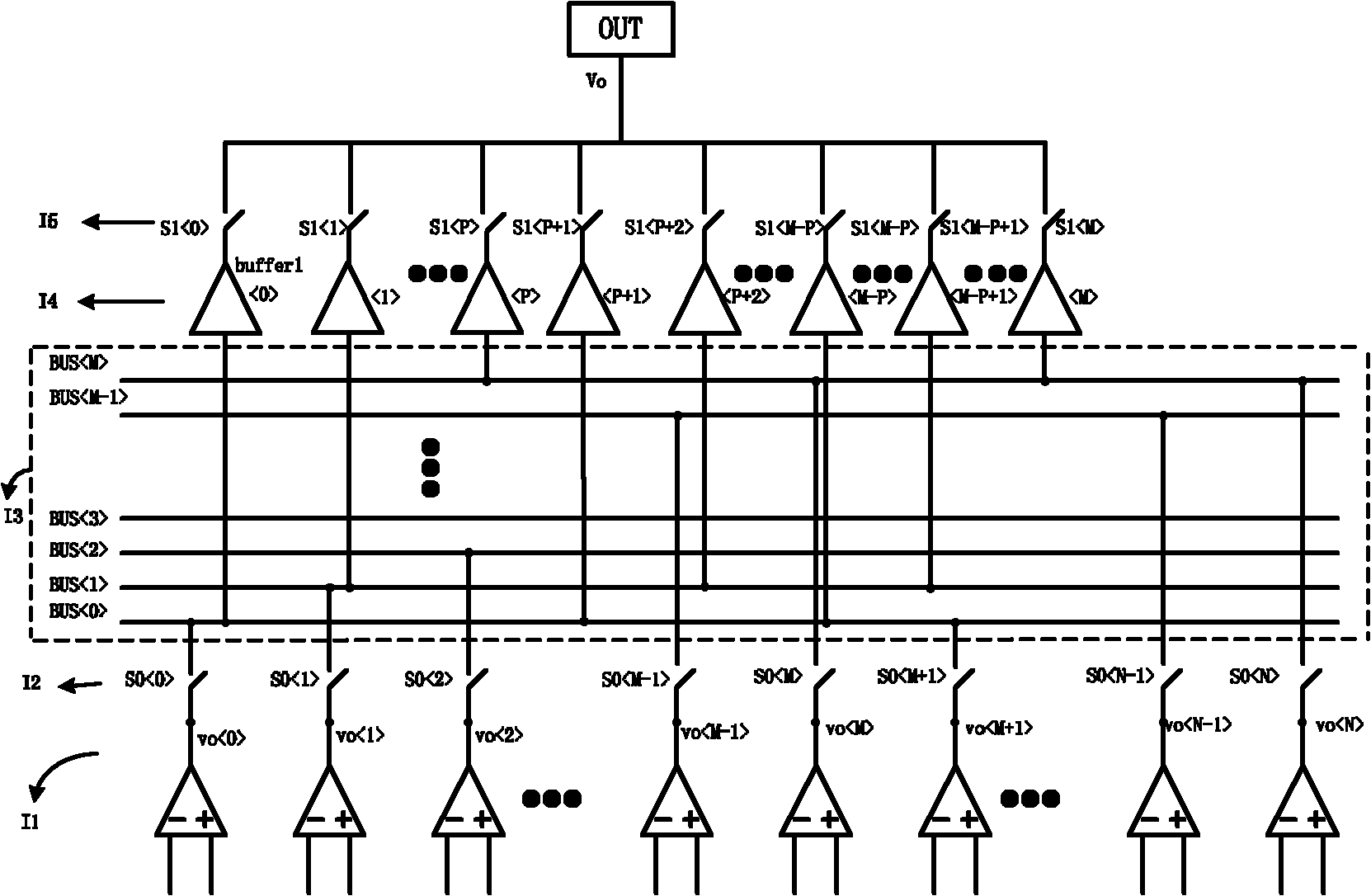
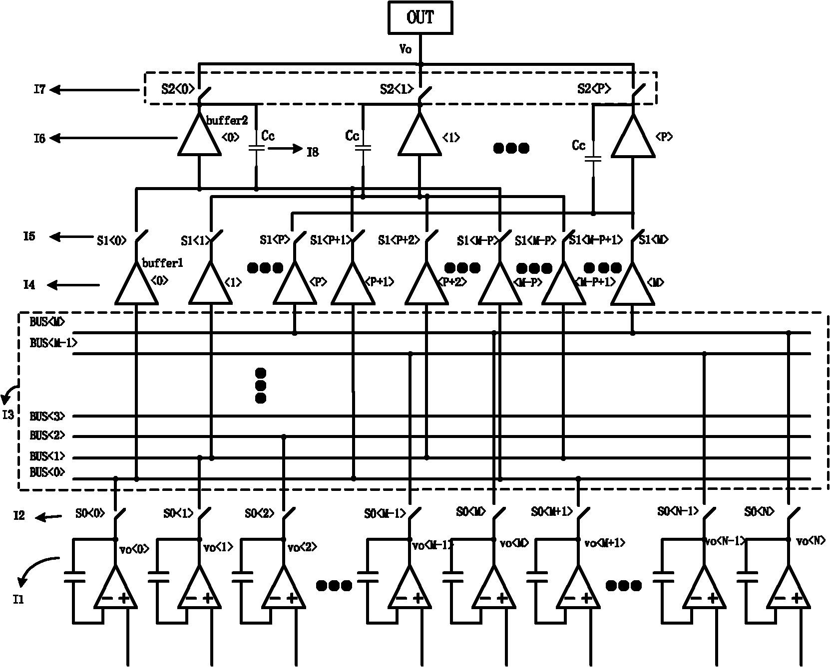
[0031] First of all, it should be noted that, without affecting the clear description of the present invention, some reference signs will be simplified, for example figure 2 The reference number of the first first stage analog output buffer shown is buffer1 , The subsequent first-level analog output buffer is only marked as - ; In addition, in order to meet the needs of some parts describing the whole part or some parts describing the individual parts, the names of some parts may also be changed. For example, in some places below, the first-level switch I2 will be called switch S0 or S0 , S0 -S0 .

[0032] Such as figure 2 As shown, the infrared focal plane array read-out circuit of the present invention includes column control signal generation logic (not shown in the figure), an output node OUT, and N+1 amplifiers I1 for amplifying current signal...


PUM


Abstract

The invention discloses an IRFPA (Infrared Focal Plane Array) and a read-out circuit thereof. The read-out circuit comprises output nodes, N+1 amplifiers, N+1 primary switches and a column control signal generating logic and also comprises M+1 output buses and M+1 primary analog output buffers, wherein the N+1 amplifiers are uniformly divided into M+1 groups, one amplifier of each group of amplifiers is respectively connected to each output bus through a primary switch, the input ends of the M+1 primary analog output buffers are respectively connected to the M+1 output buses, the output ends of the M+1 primary analog output buffers are respectively connected with the output nodes through secondary switches; and the control signals of the primary switches and the secondary switches are generated by a column control signal generating module, wherein M and N are natural numbers, and N+1 is the integral multiple of M+1. An analog voltage can be accurately output to the outside of a chip at a high speed, and power consumption is lower.

Description

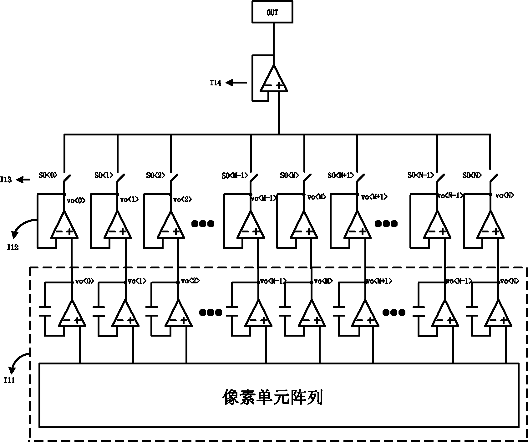
Technical field [0001] The present invention relates to the technical field of microelectronics and optoelectronics, in particular to an infrared focal plane array (infrared focal plane array) readout integrated circuit, and in particular to an infrared focal plane array with the readout circuit. Background technique [0002] Infrared imaging technology has important applications in military, industry and agriculture, medicine, astronomy and other fields. As the core of infrared imaging technology, the infrared focal plane array includes two parts: an infrared detector array and a readout circuit. The function of the detector array is to realize photoelectric conversion, and the function of the readout circuit is to complete the processing and readout of pixel signals. Among them, the readout circuit has an important influence on the performance of the infrared imaging system. [0003] The existing infrared focal plane array readout circuit such as figure 1 As shown, it includes ...

Claims


Application Information

Patent Timeline
Patent Type & Authority Applications(China)
IPC IPC(8): G01J5/10G01J5/02
Inventor 刘俊雷述宇
Owner 北方广微科技有限公司
Learn More