Waterproof slide fastener and apparatus for manufacturing the same
- Summary
- Abstract
- Description
- Claims
- Application Information
AI Technical Summary
Benefits of technology
Problems solved by technology
Method used
Image
Examples
first embodiment
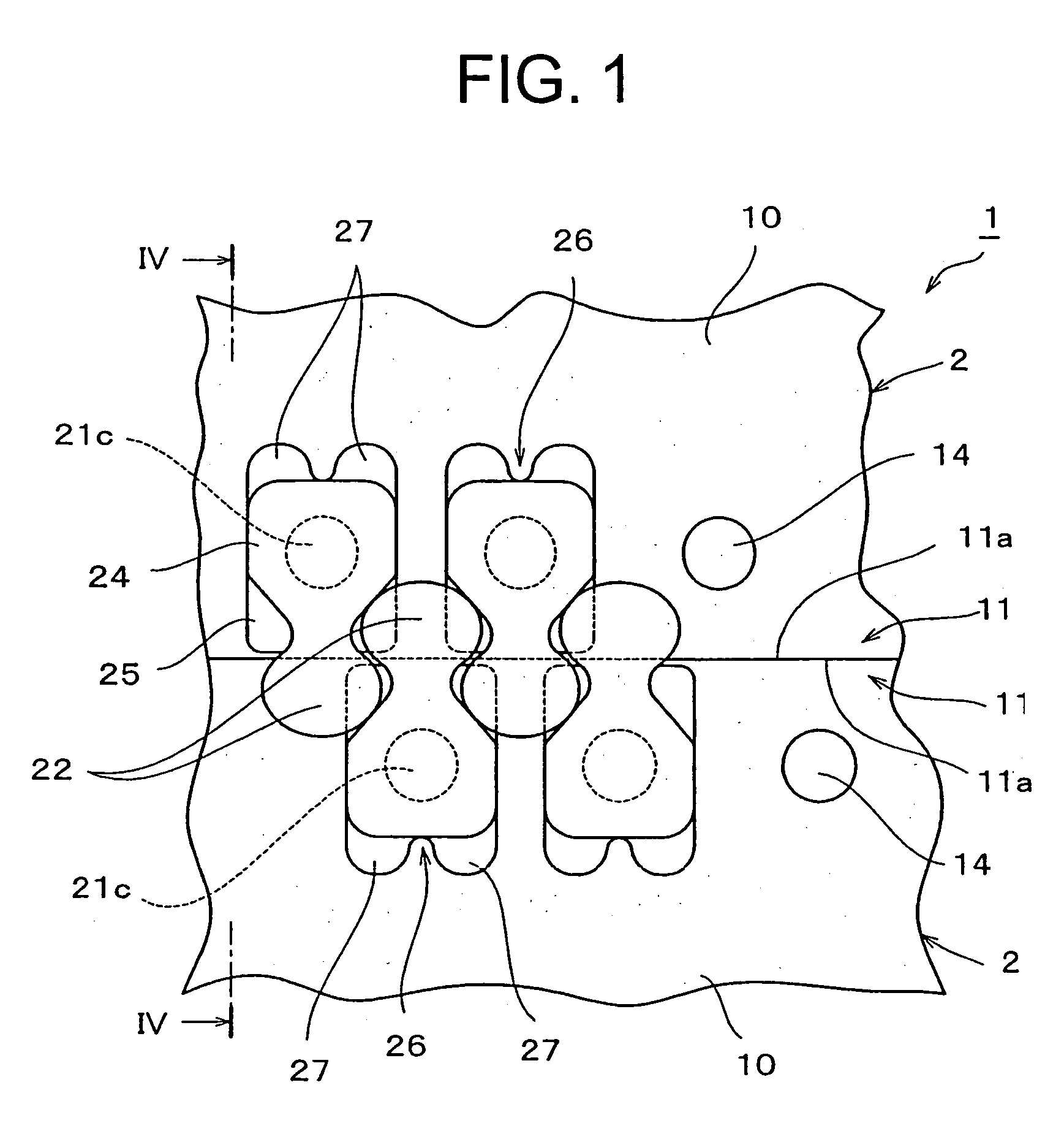
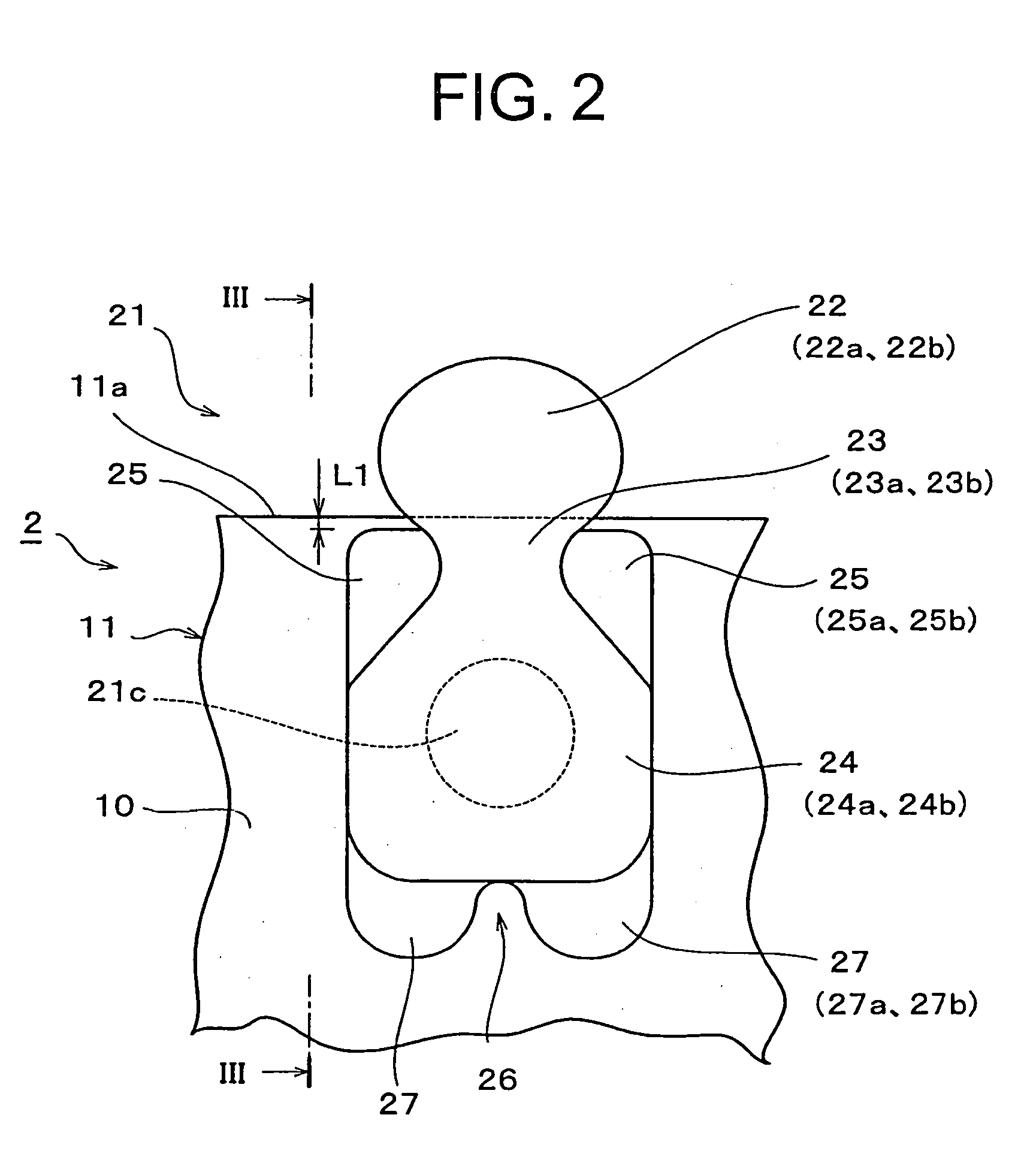
[0040]FIG. 1 is a plan view showing part of a waterproof slide fastener according to a first embodiment of the present invention. FIG. 2 is a plan view of a fastener element having a feature portion of the present invention applied to the same slide fastener. FIG. 3 is a side view of the same element. Although the present invention naturally includes an airtight slide fastener, the waterproof slide fastener is exemplified for this embodiment.
[0041] In a slide fastener 1 of this embodiment, a plurality of fastener elements 21 are formed integrally with a coupling interval with respect to each mating fastener element 21 along an element mounting edge portion 11 which is a side edge portion of a waterproof fastener tape 10, so as to form a fastener element row. Further, the slide fastener 1 is provided with synthetic resin made or metallic slider and top and bottom end stops having an ordinary structure, although not shown in the figures.
[0042] The waterproof fastener tape 10 is prod...
second embodiment
[0055]FIGS. 6 and 7 show a second embodiment of the present invention.
[0056] This embodiment is different from the first embodiment only in that an entire shoulder width L2 between right and left ends of the right and left shoulder portions 25 is set larger than a body width L3 of the body portion 24. According to this embodiment, the conventional single fin piece may be used instead of the two leg portions 27, 27. Because the entire shoulder width L2 is set larger than the body width L3, a surface area of the shoulder portion 25 increases, so that a contact area between a surface of the shoulder portion 25 and an inside face of the coupling head 22 increases, thereby intensifying waterproofness.
[0057]FIGS. 8 and 9 show modifications of the shoulder portion 25. According to these modifications, volumes of the upper and lower half portion molding cavities 34d, 35d of the shoulder portion 25 to be formed in the injection molding die 30 increase by an amount corresponding to an incre...
third embodiment
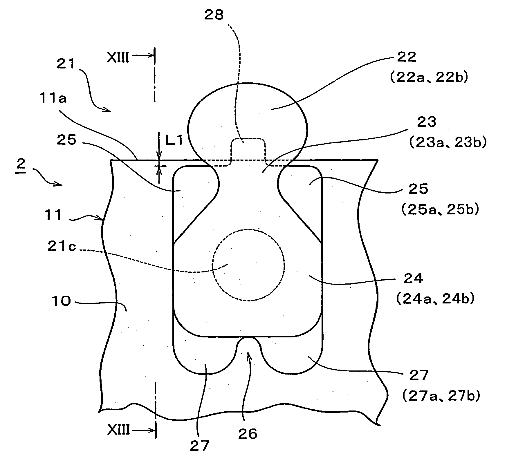
[0059] FIGS. 11 to 15 show a third embodiment of the present invention. According to this embodiment, a pair of protrusions 28 are provided in a center of each of opposing faces of respective half portions 22a, 22b of the coupling heads 22 extending outward in parallel from the element mounting edge portion 11 of the fastener tape 10 with the gap, the protrusions being started from a coupling head side end of each of the upper and lower half portions 23a, 23b of the neck portion 23 and extending toward a vertex of each of the half portions 22a, 22b of the coupling heads 22 up to halfway thereof. A width of each protrusion 28 is set to such a dimension which allows both the right and left side faces of the protrusion 28 of one coupling head 22 to be located between adjoining shoulder portions 25, 25 of a mating fastener elements when respective fastener elements engage each other. The width, an extension length and a shape of the protrusion 28 are determined under a condition in whic...
PUM
 Abstract
Description
Claims
Application Information
 - R&D
- Intellectual Property
- Life Sciences
- Materials
- Tech Scout
- Unparalleled Data Quality
- Higher Quality Content
- 60% Fewer Hallucinations
Browse by: Latest US Patents, China's latest patents, Technical Efficacy Thesaurus, Application Domain, Technology Topic, Popular Technical Reports.
© 2025 PatSnap. All rights reserved.Legal|Privacy policy|Modern Slavery Act Transparency Statement|Sitemap|About US| Contact US: help@patsnap.com


