
Methods and apparatus for achieving thermal management using processor manipulation

a technology of processors and methods, applied in multi-programming arrangements, instruments, generating/distributing signals, etc., can solve the problems of increasing processing speeds, adversely affecting the processing capability of electronic components, and complex computing systems, and achieve the effect of reducing clock speeds

Active Publication Date: 2005-09-29
SONY COMPUTER ENTERTAINMENT INC
View PDF19 Cites 120 Cited by
  • Summary
  • Abstract
  • Description
  • Claims
  • Application Information

AI Technical Summary

Benefits of technology

The present invention provides methods and systems for processing operations in a way that takes into account the thermal characteristics of the processing devices. This allows for efficient use of processing resources and reduces the likelihood of overheating and damage to components. The methods and systems involve transferring operations to other processing devices if the current processing device exceeds its thermal threshold during execution of the operation. The processing devices may include processing elements and sub-processing units with local stores for managing operations. The invention also provides priority queues for managing operations and allows for cooling down or increasing the clock speed of processing devices to manage thermal loads. Overall, the invention provides more efficient and reliable processing capabilities.

Problems solved by technology

Computing systems are becoming increasingly more complex, achieving higher processing speeds while at the same time shrinking component size and densely packing devices on a computer chip.
Excessive heat can adversely impact the processing capability of an electronic component such as a computer chip.
For example, if one area of the chip is performing computationally intensive tasks, that area can heat up significantly and form a hot spot relative to the rest of the chip.
If the hot spot exceeds a thermal threshold, the performance of the components or devices in that area of the chip may be degraded, or the chip may even become damaged or destroyed.
However, heat sinks are bulky and may merely serve to expel heat from the chip and into the volume of space surrounding the chip.
When the chip is stored in an enclosure, such as personal computer cabinet, this heat must be removed such as by the use of fans, which themselves take up space and generate unwanted noise.
Other, more complex heat management schemes also exist.
Unfortunately, this feedback approach may function too slowly or unreliably to prevent overheating.
Unfortunately, all of these techniques directly impact the speed at which the component operates, and can be detrimental to real-time processing needs.

Method used


Image

  • Methods and apparatus for achieving thermal management using processor manipulation
  • Methods and apparatus for achieving thermal management using processor manipulation
  • Methods and apparatus for achieving thermal management using processor manipulation

Examples


Embodiment Construction

[0043] In describing the preferred embodiments of the invention illustrated in the drawings, specific terminology will be used for the sake of clarity. However, the invention is not intended to be limited to the specific terms so selected, and it is to be understood that each specific term includes all technical equivalents that operate in a similar manner to accomplish a similar purpose.

[0044] Reference is now made to FIG. 3A, which is a block diagram of a basic processing module or processor element (PE) 300 that can be employed in accordance with aspects of the present invention. As shown in this figure, the PE 300 preferably comprises an I / O interface 302, a processing unit (PU) 304, a direct memory access controller (DMAC) 306, and a plurality of sub-processing units (SPUs) 308, namely SPUs 308a-308d. While four SPUs 308a-d are shown, the PE 300 may include any number of such devices. A local (or internal) PE bus 320 transmits data and applications among PU 304, the SPUs 308, ...


PUM


Abstract

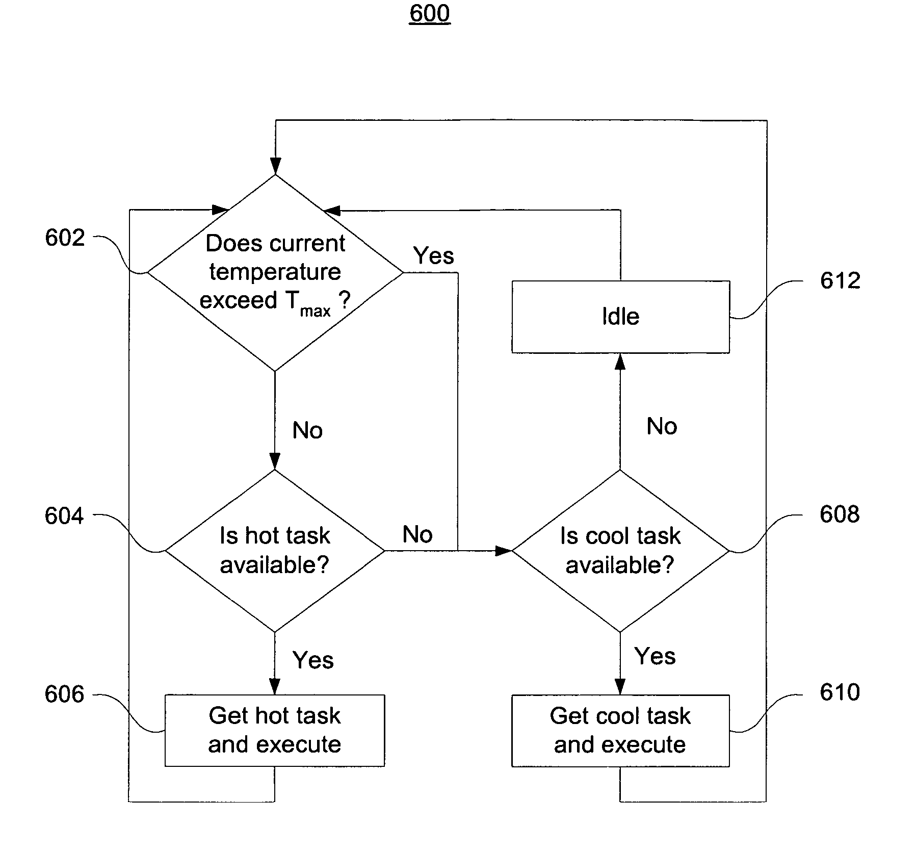
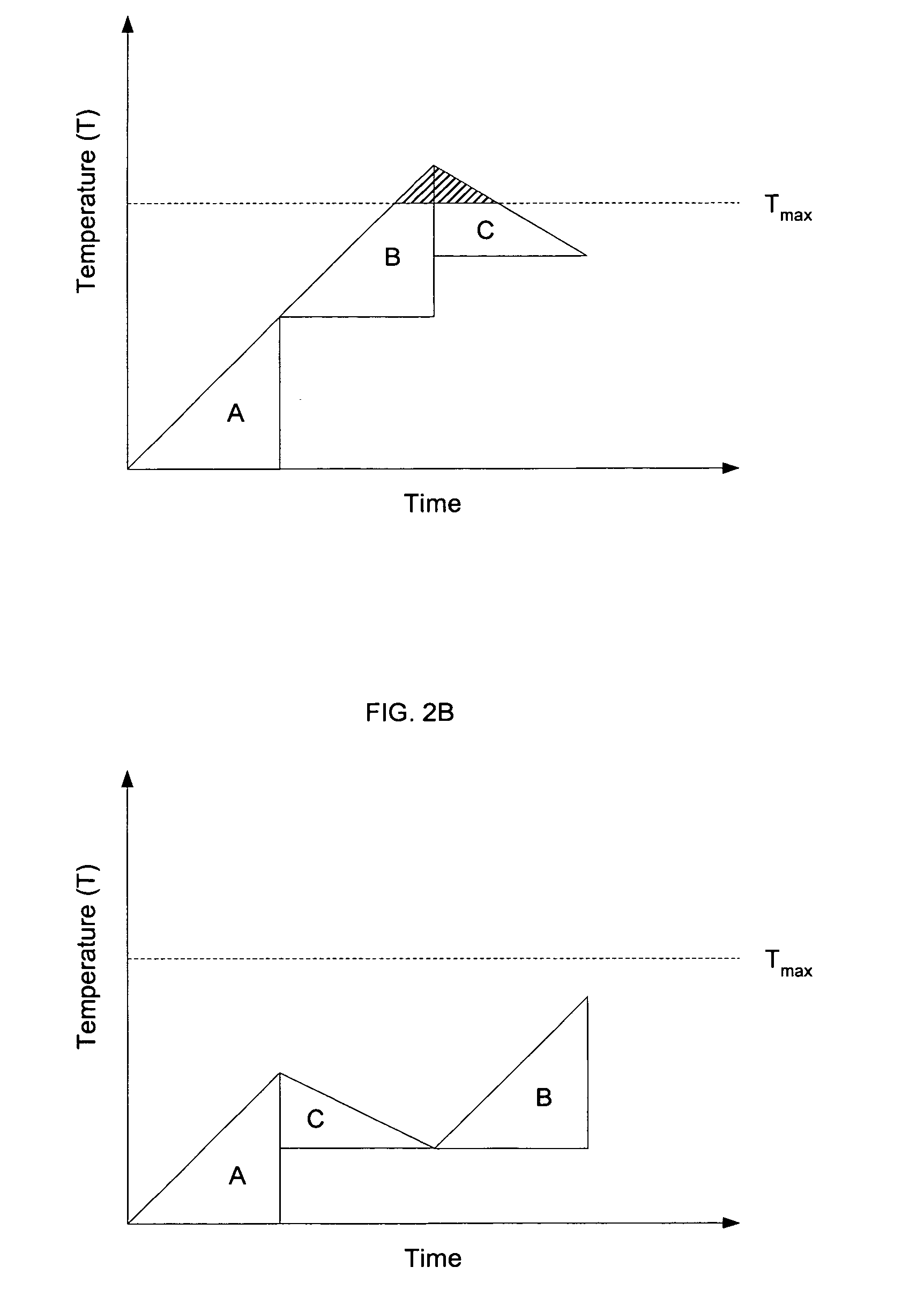
The present invention provides apparatus and methods to perform thermal management in a computing environment. Thermal attributes are associated with operations and / or processing components. The components have thermal thresholds that should not be exceeded. In a preferred embodiment, an operation can be transferred from one component to another component if the thermal threshold is exceeded during execution by the first component.

Description

CROSS-REFERENCE TO RELATED APPLICATIONS [0001] This application is related to commonly assigned U.S. patent application Ser. No. ______, entitled “Methods and Apparatus for Achieving Thermal Management Using Processing Task Scheduling,” filed Mar. 29, 2004, and incorporated by reference herein.BACKGROUND OF THE INVENTION [0002] The present invention relates to methods and apparatus for performing thermal management in a processing environment, and, in particular, for reducing thermal hot spots by effectively allocating instructions and tasks. [0003] Computing systems are becoming increasingly more complex, achieving higher processing speeds while at the same time shrinking component size and densely packing devices on a computer chip. Such advances are critical to the success of many applications, such as real-time, multimedia gaming and other computation-intensive applications. Often, computing systems incorporate multiple processors that operate in parallel (or at least in concert...

Claims


Application Information

Patent Timeline
Patent Type & Authority Applications(United States)
IPC IPC(8): G06F1/20G06F1/04G06F9/50
CPCG06F1/206
Inventor INOUE, KEISUKE
Owner SONY COMPUTER ENTERTAINMENT INC
Learn More