
Electronic access control device

a technology of electronic access control and vending machine, which is applied in the direction of anti-theft devices, program control, instruments, etc., can solve the problems of difficult code burning after the device has been manufactured, interrupt the manufacturing process, and difficulty in programming non-volatile memory, so as to improve security, facilitate manufacturing, and be more reliable to operate

Inactive Publication Date: 2005-09-29
O S SECURITY
View PDF99 Cites 52 Cited by
  • Summary
  • Abstract
  • Description
  • Claims
  • Application Information

AI Technical Summary

Benefits of technology

"The present invention provides an electronic access control device that is easier to manufacture, more reliable, and provides better security against tampering or unauthorized access. The device has a non-volatile memory for storing an access code, which can be easily inserted and read by the manufacturer. The device also has a communication port for accessing the non-volatile memory, which reduces the number of pin connections required and minimizes power consumption. The device has a low-battery detection circuit that does not consume energy when in sleep mode. The invention also provides an effective solution to the problem of intensive power consumption of the solenoid. The device uses a dual-microprocessor arrangement with two microprocessors for increased security against tampering. The invention also includes a low-battery detection circuit that is turned off and does not consume electrical power when in sleep mode. The invention also provides a vending machine with a field-programmable electronic lock that can learn a key code from an electronic key or an electronic switch controlled by a mechanical lock."

Problems solved by technology

There are problems associated with previous electronic access control devices.
One area of problems concerns the manufacture of the devices, including the difficulty in programming the non-volatile memory, such as the EPROM, for storing the access code and other useful information for the operation of the device.
EPROMs, which usually require parallel programming, interrupt the manufacturing process in that they restrict when the manufacturer can program the device.
However, with parallel EPROMs, burning in the code after the device has manufactured is difficult.
After the device is soldered together, the manufacturer must contend with integrated circuit pin clips and must worry about interference with other circuitry on the manufactured device.
Further, manufacturing, with known electronic access control devices, requires many pin connections which increase manufacturing cost.
When the device contains a significant number of pin connections, the reliability of the device decreases.
However, with parallel EPROMs, serial access is not available.
One common problem associated with previous electronic locks is their potential vulnerability to tampering.
This arrangement is vulnerable to tampering because if the control circuit is somehow broken in or removed, one can open the lock by “hot-wiring” the control lines for activating the lock-opening mechanism.
Another technically challenging problem is related to the need to provide electrical energy to power the operation of the electronic access control device.
A battery, however, has a rather limited amount of electrical energy stored therein.
The operation of the low-battery detection circuit, however, also consumes electrical energy and contributes to the draining of the battery.
Although electronic keys are a convenient feature, they have their associated problems.
One problem is related to the unauthorized use of the keys.
There is a danger that such a master key may be used for unauthorized opening of other safes in the hotel.
Another problem associated with the use of an electronic key or a wireless access code transmitter is that the key or the transmitter may be lost easily, or the user may simply forget to bring the key or transmitter.
This problem is especially serious if the electronic access control device does not provide other means, such as a keypad, for entering the access code.
One significant problem with conventional vending machines is the difficulties in managing the distribution and usage of the keys to ensure the security of the locks on the vending machines.
The process of collecting money from the vending machines scattered at different places is a very manpower-intensive operation that requires many employees to go into the field with numerous mechanical keys for operating the locks on the vending machines.
It requires a considerable amount of attention and efforts to manage and track the distribution of the keys to the field workers to keep the keys secure.
Moreover, the mechanical keys and lock cores of vending machines are a point of attack for vandals.
The keys can be lost or copied easily, and the stolen or copied keys may then be used by an unauthorized person to access the machines, and it is difficult to discover such misuses and security breaches.
Also, a skilled vandal can easily pick or drill-out the lock core tumblers and measure the key cuts of the lock core tumblers to re-produce a like key and compromise the security.
In the event a security breach is identified, the mechanical lock cores of the affected vending machines typically have to be manually replaced, which is a time-consuming and very costly process.
Furthermore, mechanical keys and locks are devices that cannot be partially limited in operation they operate indefinitely if in use.
Also, they do not have the ability to record access operation attempts of their operation.

Method used


Image

  • Electronic access control device
  • Electronic access control device
  • Electronic access control device

Examples


Embodiment Construction

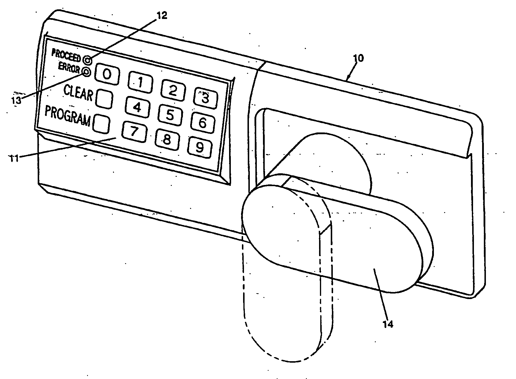
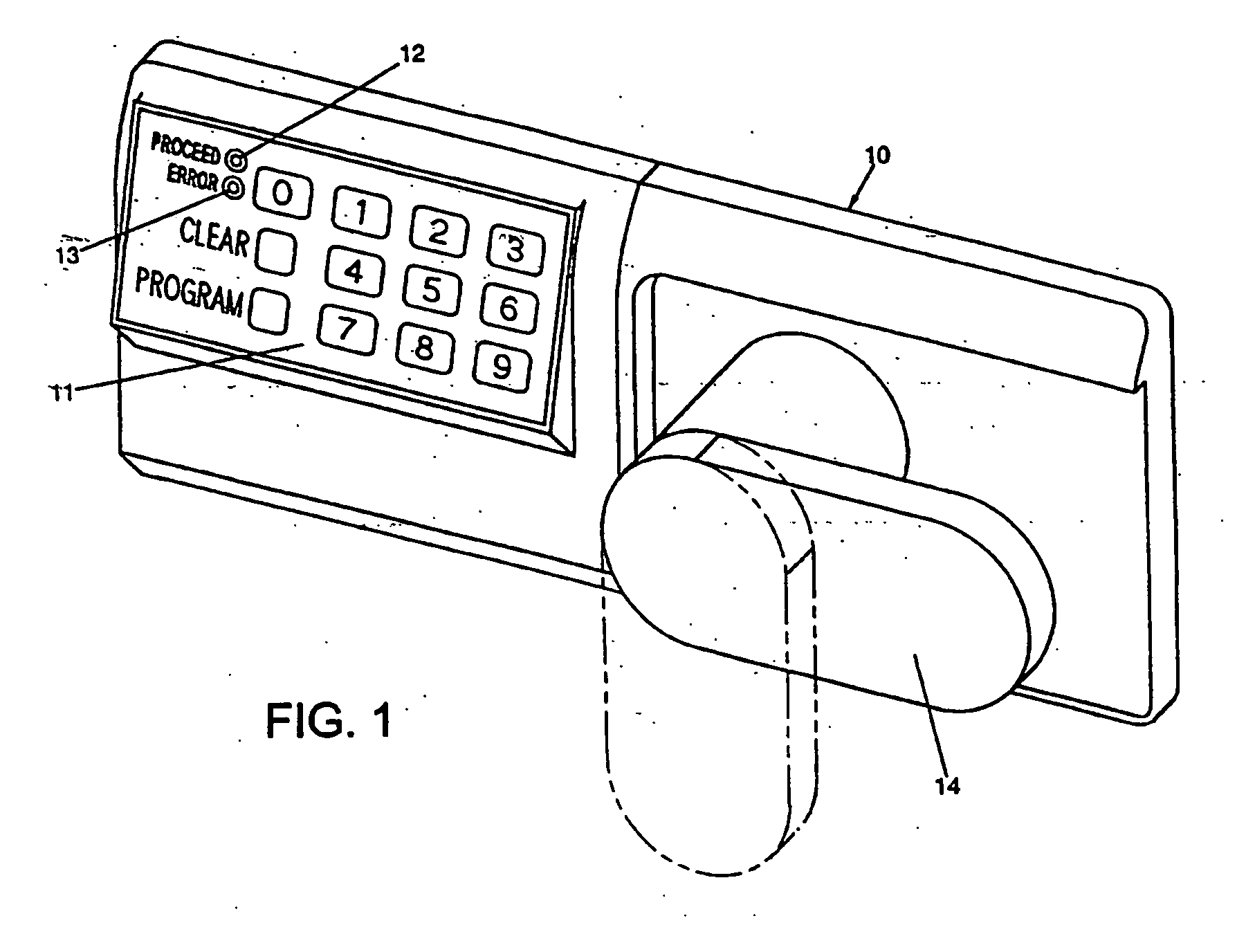
[0073] Referring to the drawings, there is shown in FIG. 1 an illustrative electronic access control device 10 having a keypad 11, light emitting diodes (LEDs) 12 and 13, and a mechanical lever arm 14. In this illustration, the device is used as a lock for an office safe. The device can also be applied to various applications including locks for vending machines or amusement games.

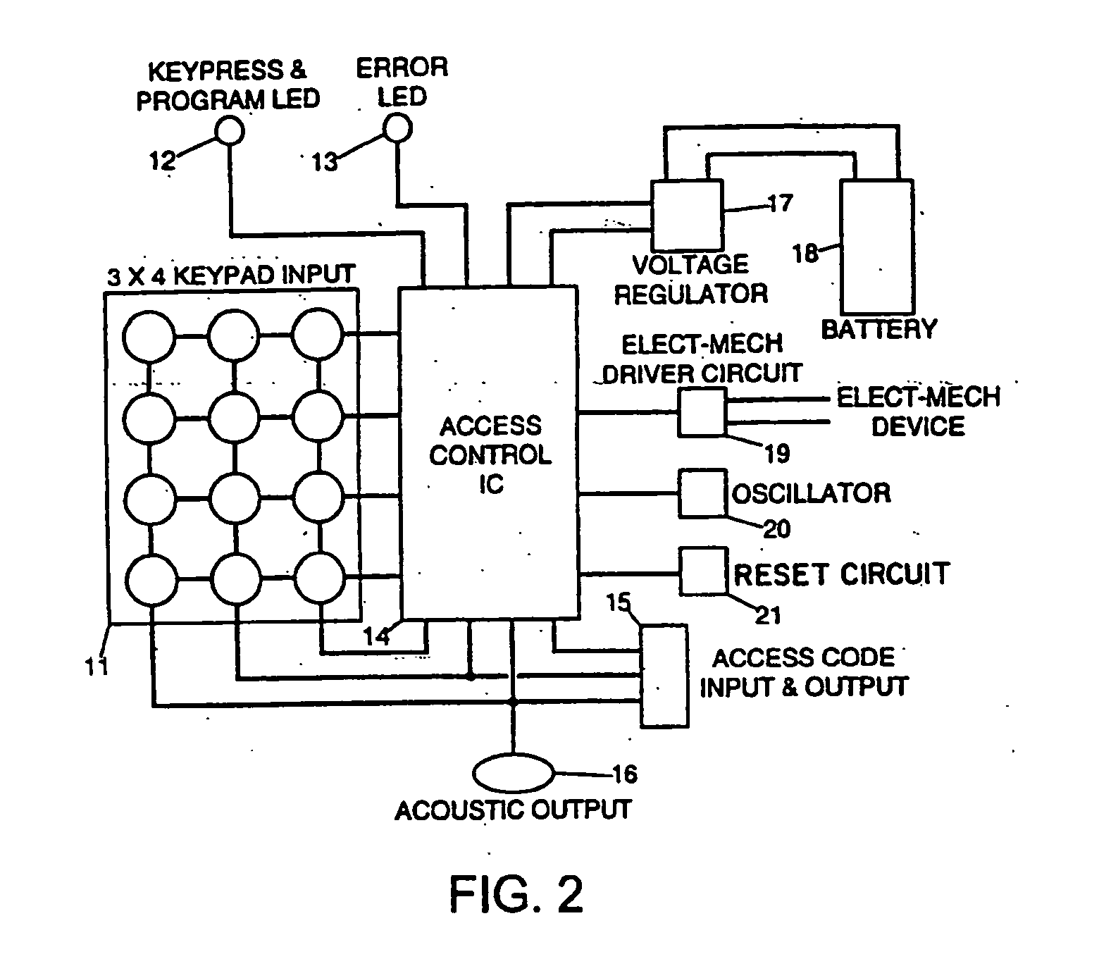
[0074] The main components of the electronic access code device are shown in FIG. 2 which include a keypad 11, a microprocessor 14, an access code input and output 15, an acoustic output (a piezo ceramic bender, Model No. KB1-1541) 16, LEDs 12 and 13, a voltage regulator (LM2936Z-5.0) 17, a battery 18, an electromechanical driver output 19, an oscillator 20, and a reset circuit 21. Inputs to the device may take the form of a thumbprint scan, a retinal scan, or a magnetic strip input which may work in conjunction with a keypad or as a sole means of input. Outputs may take the form of an alpha-numeric displ...


PUM


Abstract

An electronic access control device is disclosed comprising two microprocessors. The first microprocessor receives a wirelessly transmitted that is compared to a stored access code. If those two codes match, the first microprocessor transmits a special communication code to the second microprocessor. The second microprocessor opens the lock if the transmitted communication code matches a stored communication code.

Description

RELATED APPLICATIONS [0001] This application is a continuation-in-part of co-pending U.S. patent application Ser. No. 10 / 885,998, filed Jul. 7, 2004, which is a continuation of co-pending U.S. patent application Ser. No. 10 / 024,945, filed Dec. 19, 2001, which is a continuation of U.S. patent application Ser. No. 08 / 760,062, filed Dec. 4, 1996, and issued as U.S. Pat. No. 6,359,547, which is a continuation-in-part of U.S. patent application Ser. No. 08 / 339,555, filed Nov. 15, 1994, and issued as U.S. Pat. No. 5,617,082. [0002] This application is also a continuation-in-part of co-pending U.S. patent application Ser. No. 10 / 329,626, filed Dec. 26, 2002, which claims the benefit of U.S. Provisional Patent Application Ser. No. 60 / 344,221, filed Dec. 27, 2001.FIELD OF THE INVENTION [0003] This invention relates generally to access control devices for vending machines, and more particularly to an electronic access control device for a vending machine, or the like, wherein the device is co...

Claims


Application Information

Patent Timeline
Patent Type & Authority Applications(United States)
IPC IPC(8): G07C9/00G07F7/10H04L9/32
CPCB60R25/102B62H5/20G07C9/00142G07C9/00182G07C9/00571G07F7/1025G07C9/00896G07C9/00912G07C2009/00793G07F7/1008G07C9/0069Y10T70/7006Y10T70/7113G07C9/33H04Q1/00
Inventor DENISON, WILLIAM D.SILVERS, BRADLEY S.BROWNFIELD, LAWRENCE
Owner O S SECURITY
Learn More