
Determination of the gas pressure in an evacuated thermal insulating board (vacuum panel) by using a heat sink and test layer that are intergrated therein

a technology of thermal insulation board and gas pressure, which is applied in the direction of fluid tightness measurement, heat measurement, instruments, etc., can solve the problems of gas pressure of vacuum insulation board, inexactness, prone to false, etc., and achieve the effect of suppressing heat and reducing heat loss of sensor body

Active Publication Date: 2005-09-15
VA Q TEC AG
View PDF4 Cites 11 Cited by
  • Summary
  • Abstract
  • Description
  • Claims
  • Application Information

AI Technical Summary

Benefits of technology

The invention is a measurement apparatus that includes a device that is installed between the insulating core and the covering shell of a thermal insulating board. The device has a heat sink with a high thermal conductivity and a large volume-related thermal capacity, which changes as the gas pressure in the vacuum panel changes. The apparatus includes a test layer with a defined thermal conductivity that changes as the gas pressure in the panel changes. By measuring the heat flow through the test layer, the gas pressure can be determined. The invention allows for the rapid "In-line-check" of gas pressure after production of the vacuum panels. The thermal conductivity of the test layer is determined by its thickness and the gas pressure level. The invention can be used with various types of insulating materials and can be cost-effective.

Problems solved by technology

While such methods enjoy a relative precision, lying below 5% in relation to the absolute thermal conductivity, they are nevertheless extremely time consuming.
On the other hand, hitherto available non-stationary techniques, which involve impressing a board with a heat or temperature pulse and measuring such values like temperature or heat flow in a time dependent manner, are faster than the stationary techniques, but they tend to be inexact and prone to false results.
Moreover, the gas pressure of a vacuum insulating board that has been committed or already built into an insulating object can no longer be determined, so other methods must be found for these purposes.
Furthermore, wherever possible every attention must be paid that the production costs of the vacuum panels are not significantly raised.

Method used


Image

  • Determination of the gas pressure in an evacuated thermal insulating board (vacuum panel) by using a heat sink and test layer that are intergrated therein
  • Determination of the gas pressure in an evacuated thermal insulating board (vacuum panel) by using a heat sink and test layer that are intergrated therein

Examples


Embodiment Construction

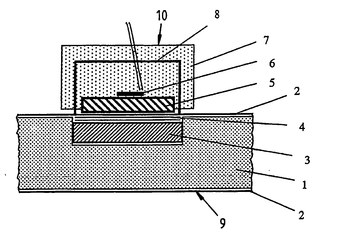
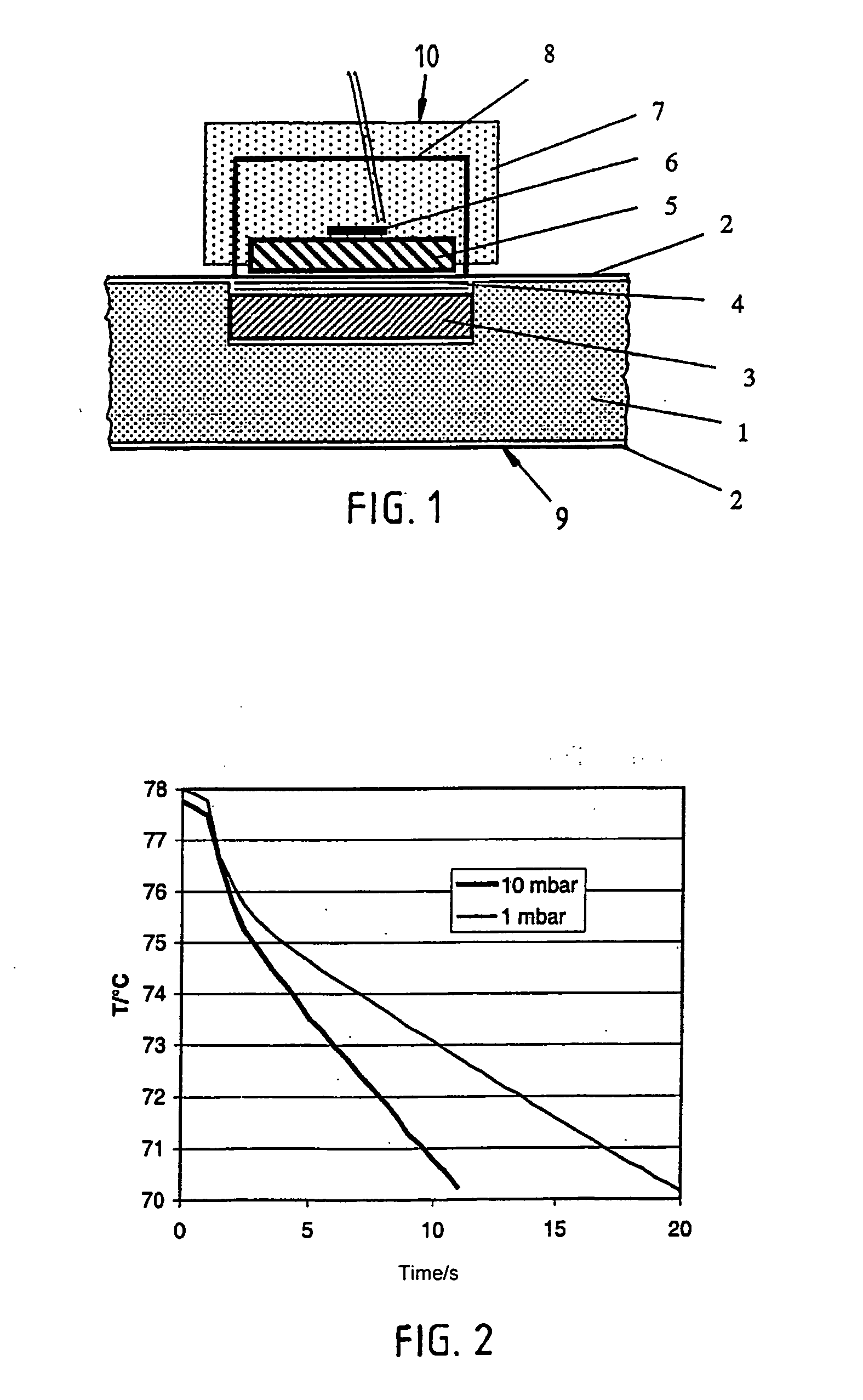
[0043] The thermal insulating board 9 from FIG. 1 consists of an insulating core 1, which is enclosed on all sides by a foil 2. In accordance with the invention, a small metal or ceramic plate 3, for example made from aluminum, is inserted during the production between the insulating core and the covering foil, and serves as a heat sink. This plate 3 can have a round, square or rectangular shape with a diameter or side length of 30 mm, for example, and a thickness of 2 mm, for example.

[0044] According to the invention, a test layer in the form of a thin porous intermediate layer 4 is placed as thermal resistance between the heat sink 3 and the covering foil 2. The pore size of the open-pored test layer 4 can be significantly larger than that of the insulating core 1, so that the gas thermal conductivity in the test layer 4 is noticeable at significantly lower gas pressures than in the insulating core 1. A thickness of only around 0.1 mm to 0.3 mm is indicated for the test layer 4. ...


PUM

PropertyMeasurementUnit
thicknessaaaaaaaaaa
thicknessaaaaaaaaaa
thicknessaaaaaaaaaa

Abstract

The invention relates to the determination of the gas pressure in an evacuated thermal insulating board (9) having an insulating core (1) covered by a film (2). The inventive device comprises an assembly, which is integrated between the insulating core and the covering film of the thermal insulating board and which has a body that acts as a heat sink (3) (Al, Co, Fe, ceramic), and the body's thermal conductivity and thermal capacity relative to volume are greater than those of the insulating core. Said assembly also comprises a test layer (4) (0.3 mm nonwoven fabric made of plastic and glass fibers), which is arranged between the heat sink and the covering film and has a defined thermal conductivity that changes according to the gas pressure inside the evacuated thermal insulating board. From the exterior, a sensor device is applied to or pressed against the test device, which is placed inside the evacuated thermal insulating board and which is covered by the covering film. Said sensor device comprises a body (5) (coppered steel 78° C., thermoelement (6)) having a distinctly different temperature than that of the test device (heat sink) whereby creating a heat flux, which is influenced by the thermal conductivity of the test layer, said thermal conductivity varying according to the gas pressure inside the thermal insulating board, and the magnitude of this heat flux is metrologically determined. The heat sink (3) can be provided in the form of a bottom part of a container for a getter material.

Description

(e) BACKGROUND OF THE INVENTION [0001] 1. Field of the Invention [0002] The invention relates to a device for performing a thermal measurement method, from which the gas pressure in an evacuated thermal insulating board can be determined where this latter has an insulating core enclosed in a film. Likewise, the invention centers on a method for measuring the gas pressure inside an evacuated thermal insulating board. [0003] 2. Description of the Related Art [0004] Evacuated thermal insulation plates or vacuum panels reach a high insulation effect with the smallest insulation thickness. Usually, they consist of an evacuable, porous core material of low thermal conductivity, and of a vacuum sealed covering shell, the latter composed, for example, of a metallized high-barrier synthetic film. For applications that require longer life spans, in building structures for example, an insulating core of microporous silica has been demonstrated to have advantages. For applications demanding sho...

Claims


Application Information

Patent Timeline
Patent Type & Authority Applications(United States)
IPC IPC(8): G01L21/10G01L21/14G01M3/00G01N25/18
CPCG01L21/10G01N25/18G01M3/002F16L59/06G01M3/26
Inventor CAPS, ROLAND
Owner VA Q TEC AG
Learn More