Eureka AIR delivers breakthrough ideas for toughest innovation challenges, trusted by R&D personnel around the world.

Apparatus for improving combustion efficiency of internal combustion engine

Inactive Publication Date: 2005-09-08
HOAMMOREA
View PDF0 Cites 4 Cited by
  • Summary
  • Abstract
  • Description
  • Claims
  • Application Information

AI Technical Summary

Benefits of technology

[0010] Accordingly, an object of the present invention is to obviate one or more problems due to limitations and disadvantages of the related art and to provide apparatus for improving combustion efficiency of an internal combustion engine, by which moisture contained in fuel is eliminated to increase the power of an operating machine and to reduce smoke due to incomplete combustion.

Problems solved by technology

At this time, incomplete combustion results from inadequate mixing of oxygen and fuel in a burning process, since there is attraction between negative charges (electrons) and positive charges (protons).
In the above pre-heating method, an additional pre-heating device should be provided to heat the fuel supplied to the combustion chamber, which increases cost and also complicates construction.
In addition, there is another drawback in that since most of the pre-heating device utilize electricity as a heat source, energy consumption is large.
Therefore, in practice, it has not been practical to use in pre-heatingdevices.
However, in the method using the permanent magnet, a magnetic force is gradually decreased by vibration of the internal combustion and an electric field.
If the magnetic force is decreased, the fuel is not sufficiently activated due to insufficient magnetization resulted from the improper relationship between an inflow speed of the fuel and contact of the magnet.

Method used


Image

  • Apparatus for improving combustion efficiency of internal combustion engine
  • Apparatus for improving combustion efficiency of internal combustion engine
  • Apparatus for improving combustion efficiency of internal combustion engine

Examples


embodiments

Embodiment 1

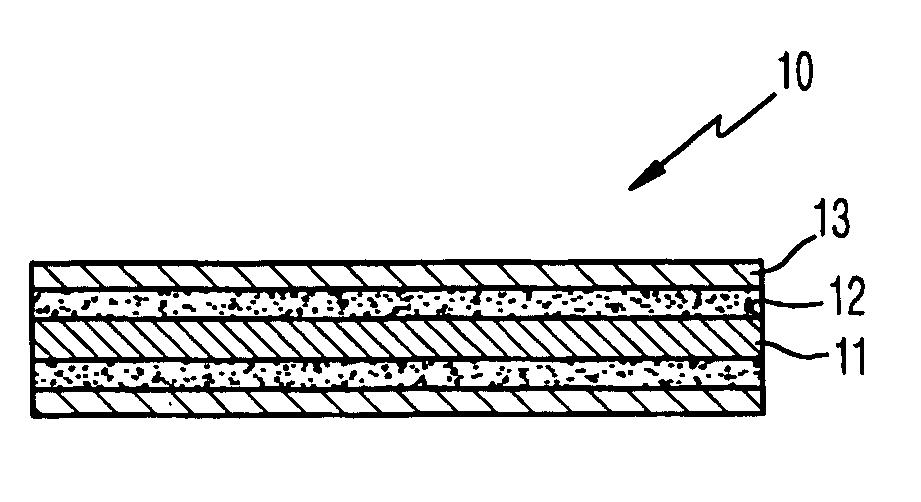
[0019] Referring to FIG. 1, the combustion-efficiency improving apparatus is adapted to be immerged to a fuel tank of an internal combustion. The apparatus includes a core rod 10 having a ceramic powder 12 coated or impregnated on an outer periphery of a silver alloy 11, and an aluminum alloy cladding the ceramic powder 12; and an internal electrode 20 enclosing an outer periphery of the core rod 10 for creating a potential difference through shifting of electrons between the internal electrode and fuel.

[0020] Specifically, the core rod 10 is enclosed by the internal electrode 20 to radiate far-infrared, as shown in FIG. 1. The core rod 10 includes the silver alloy 11 forming a core of a housing, the ceramic powder 12 coated or impregnated on the outer periphery of the silver alloy 11, and the aluminum film 13 enclosing the outer periphery of the ceramic powder 12.

[0021] The aluminum film 13 is to prevent separation of the ceramic powder 12, and is melted and alloyed ...

embodiment 2

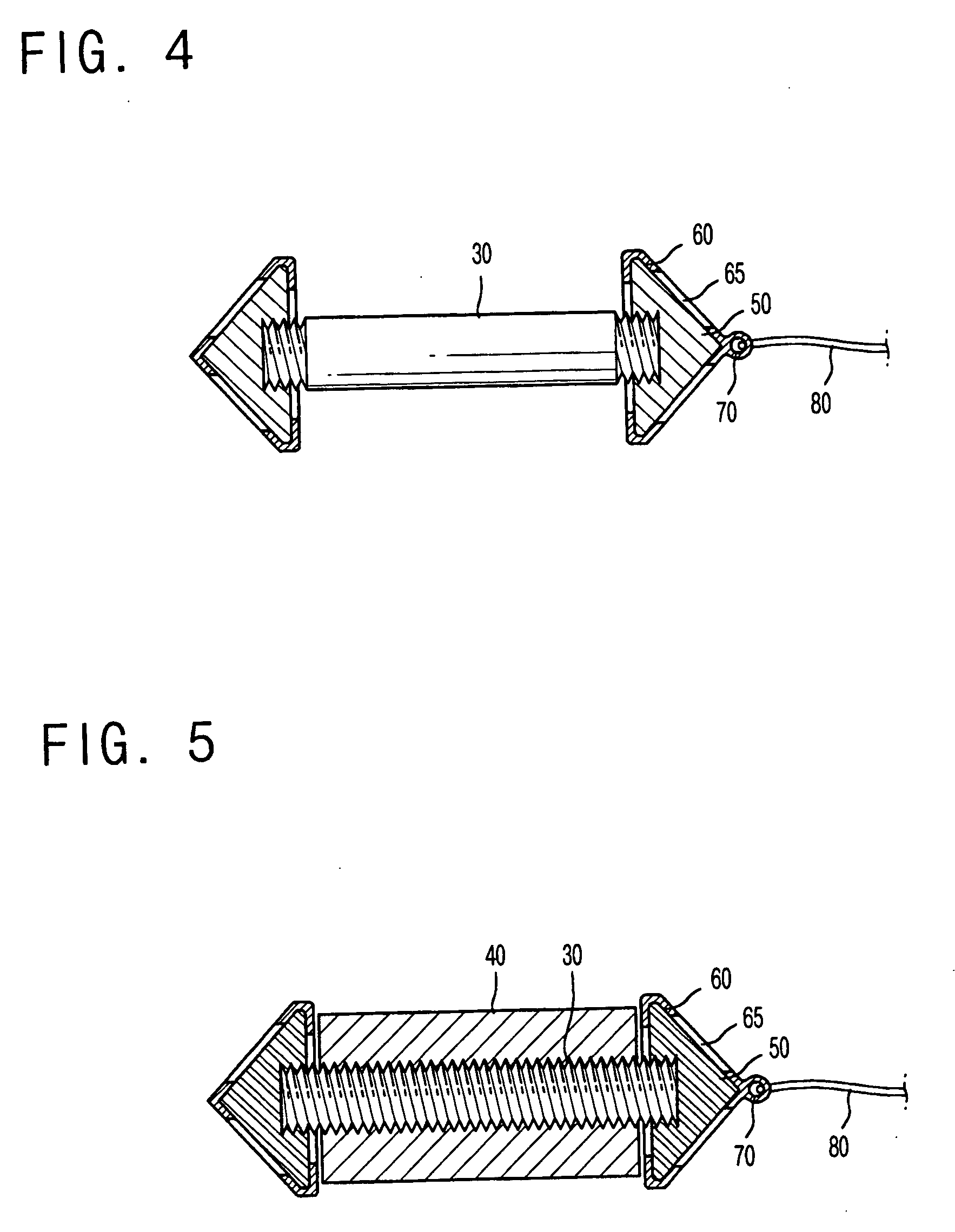
[0026] Referring to FIG. 3, the combustion-efficiency improving apparatus is adapted to be immerged into a fuel tank of an internal combustion. The apparatus includes a core rod 10 having a ceramic powder 12 coated or impregnated on an outer periphery of a silver alloy 11, and an aluminum alloy cladding the ceramic powder 12; an internal electrode 20 enclosing an outer periphery of the core rod 10 for creating a potential difference through shifting of electrons between the internal electrode and fuel; and an external electrode 40 formed on an outer periphery of the internal electrode 20.

[0027] The core rod 10 the and internal electrode 20 are substantially identical with those of the first embodiment, except that the ceramic powder 12 is coated or impregnated on or in a body of the external electrode, with the external electrode 40 being formed of a magnesium alloy. Accordingly, the detailed description of the core rod 10 and the internal electrode 20 will be omitted herein.

[0028...

embodiment 3

[0030] Referring to FIG. 4, the combustion-efficiency improving apparatus is adapted to be immerged into a fuel tank of an internal combustion. The apparatus includes a core rod 10 having a ceramic powder 12 or impregnated on an outer periphery of a silver alloy 11, and an aluminum alloy cladding the ceramic powder 12; an internal electrode 20 enclosing an outer periphery of the core rod 10 for creating a potential difference through shifting of electrons between the internal electrode and fuel; and a lateral electrode 50 formed on both ends of the core rod 10 and the internal electrode 20.

[0031] The core rod 10 and the internal electrode 20 are substantially identical with those of the first embodiment, and so the detailed description thereof will be omitted herein. Preferably, the lateral electrode 50 is formed of any one of zinc alloy, aluminum alloy and magnesium alloy.

[0032] Preferably, the lateral electrode 50 is formed in a conical shape. A female threaded portion is formed...


PUM


Abstract

Disclosed is a combustion-efficiency improving apparatus immerged into a fuel tank of an internal combustion. The apparatus includes a core rod 10 having a ceramic powder 12 coated or impregnated on an outer periphery of a silver alloy 11, and an aluminum alloy cladding the ceramic powder 12; and an internal electrode 20 enclosing an outer periphery of the core rod 10 for creating a potential difference through shifting of electrons between the internal electrode and fuel. A reduction potential of water contained in the fuel is achieved by an electromotive force and an electromagnetic wave generated from the core rod and the internal electrode. A reduction potential of the water contained in the fuel is achieved by the electromotive force and the electromagnetic wave generated from the apparatus, thereby improving the combustion efficiency of the fuel, as well as saving the fuel and minimizing the smoke.

Description

BACKGROUND OF THE INVENTION [0001] 1. Field of the Invention [0002] The present invention relates to a fuel-saving apparatus for an internal combustion engine, and more particularly, to an apparatus for improving combustion efficiency of an internal combustion engine, by which moisture contained in fuel is eliminated to increase power of an operating machine and to reduce smoke due to incomplete combustion. [0003] 2. Background of the Related Art [0004] In general, a combustion process of vehicles or boilers is implemented by forcibly injecting a liquid or a gaseous hydrocarbon into a combustion chamber. At this time, incomplete combustion results from inadequate mixing of oxygen and fuel in a burning process, since there is attraction between negative charges (electrons) and positive charges (protons). [0005] In order to solve the incomplete combustion of the fuel in the internal combustion engine, a fuel miser has been developed to accelerate activation or ionization of the fuel, ...

Claims


Application Information

Patent Timeline
IPC IPC(8): F02M27/06F02G5/00F02M27/04
CPCF02M27/04F23K2301/101F02M27/06F23K2300/101
Inventor LEE, SANG JIN
Owner HOAMMOREA
Why Eureka
Eureka Blog
Learn More