
Method and apparatus for a high performance and high dynamic range baseband power control system

a power control system and dynamic range technology, applied in power management, transmission monitoring, wireless communication, etc., can solve the problems of inability to precisely realize the requested attenuation, coarse granularity, and limited number of analog step attenuators, and achieve low power consumption, small area, and high accuracy.

Inactive Publication Date: 2005-09-01
APPLE INC
View PDF7 Cites 26 Cited by
  • Summary
  • Abstract
  • Description
  • Claims
  • Application Information

AI Technical Summary

Benefits of technology

[0008] The invention provides a method and apparatus for realizing a system to control transmit power which simultaneously allows high accuracy, small area, and low power consumption.
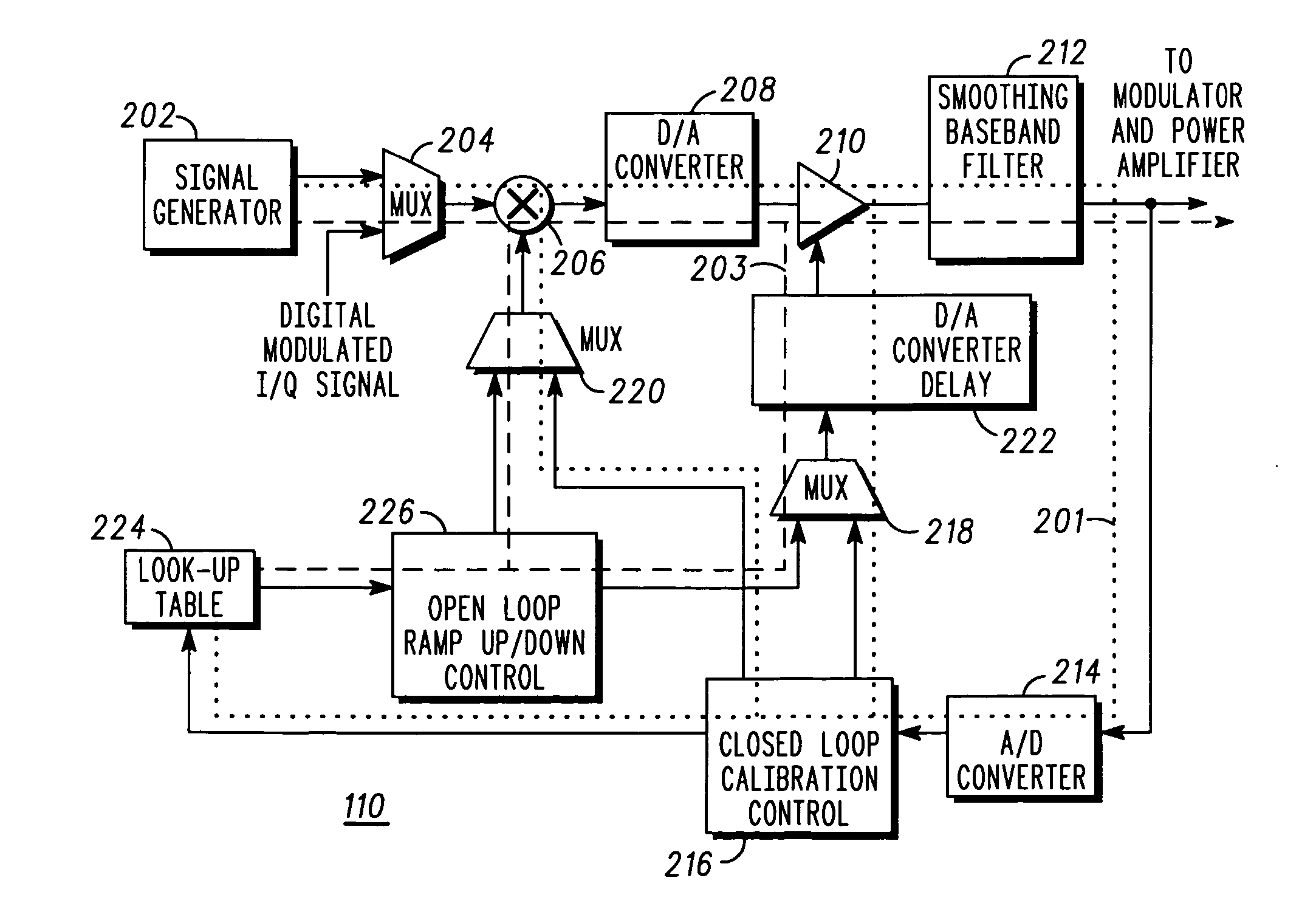
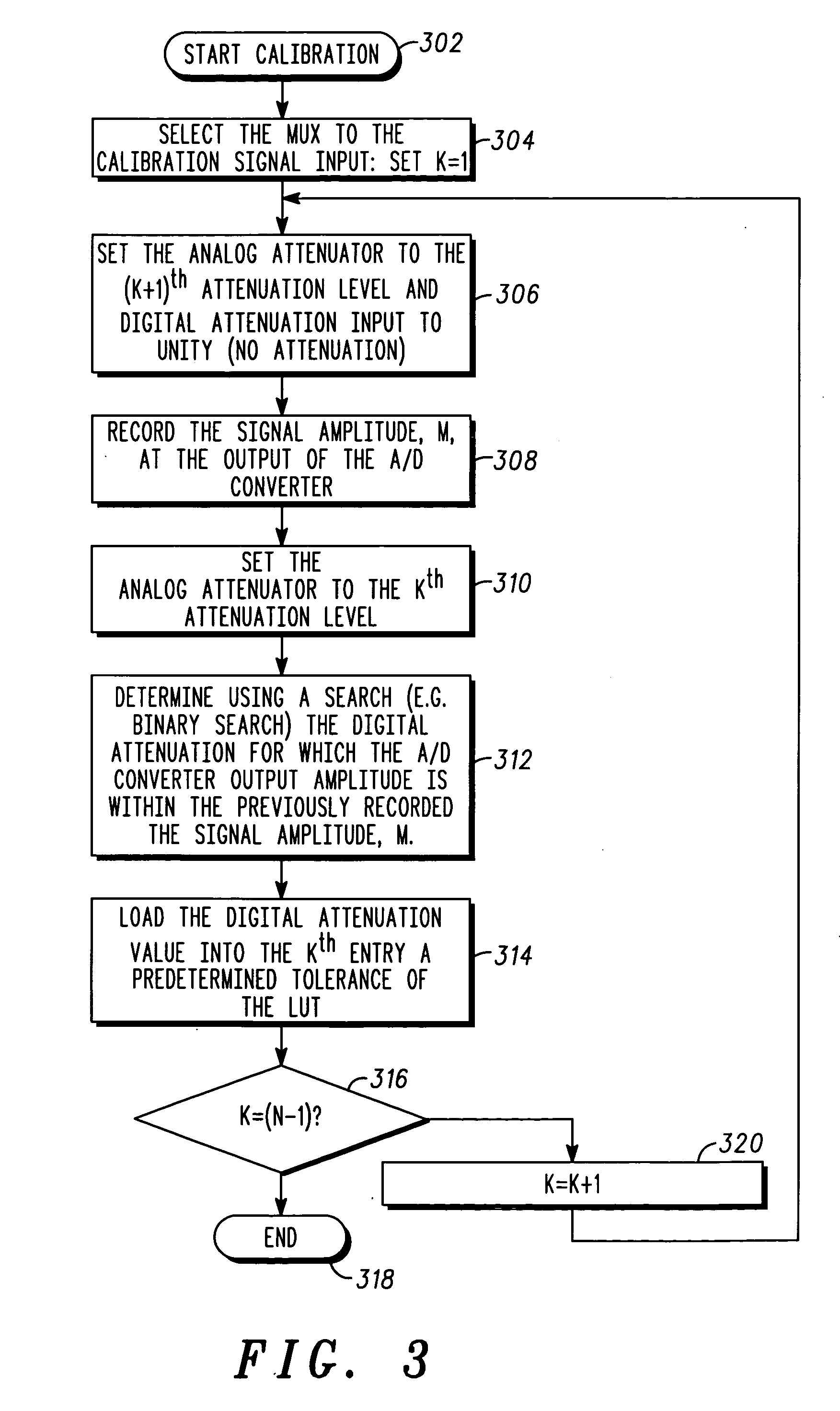
[0011] Because the attenuation steps have been accurately measured by comparison to the digital attenuator, the attenuation actually realized by the analog step attenuator is accurately known. Therefore, the difference between the attenuation realized by the analog step attenuator and the desired attenuation is accurately known. Because the difference is accurately known, the difference can be realized in a digital attenuator and the attenuation resulting from the composite of the digital and analog step attenuator can very accurately realize the requested attenuation.
[0012] The majority of the requested attenuation is realized in an analog step attenuator. Thus, after the digital to analog converter, the present invention does not require a significant increase in the dynamic range for conversion of this converter. Further, the analog step attenuator and digital attenuator do not require large area and can be low power devices. Finally, the combination realizes an accurate attenuation with very fine granularity in attenuation by using very fine precision steps.

Problems solved by technology

In general, however, the analog step attenuator still has a limited number of attenuation levels and thus, a very coarse granularity.
Therefore, it will not be able to realize the requested attenuation exactly.
Also, the coarse granularity steps that analog attenuators have will not meet transient adjacent channel leakage specifications when ramping up or down with such larger steps.

Method used


Image

  • Method and apparatus for a high performance and high dynamic range baseband power control system
  • Method and apparatus for a high performance and high dynamic range baseband power control system
  • Method and apparatus for a high performance and high dynamic range baseband power control system

Examples


Embodiment Construction

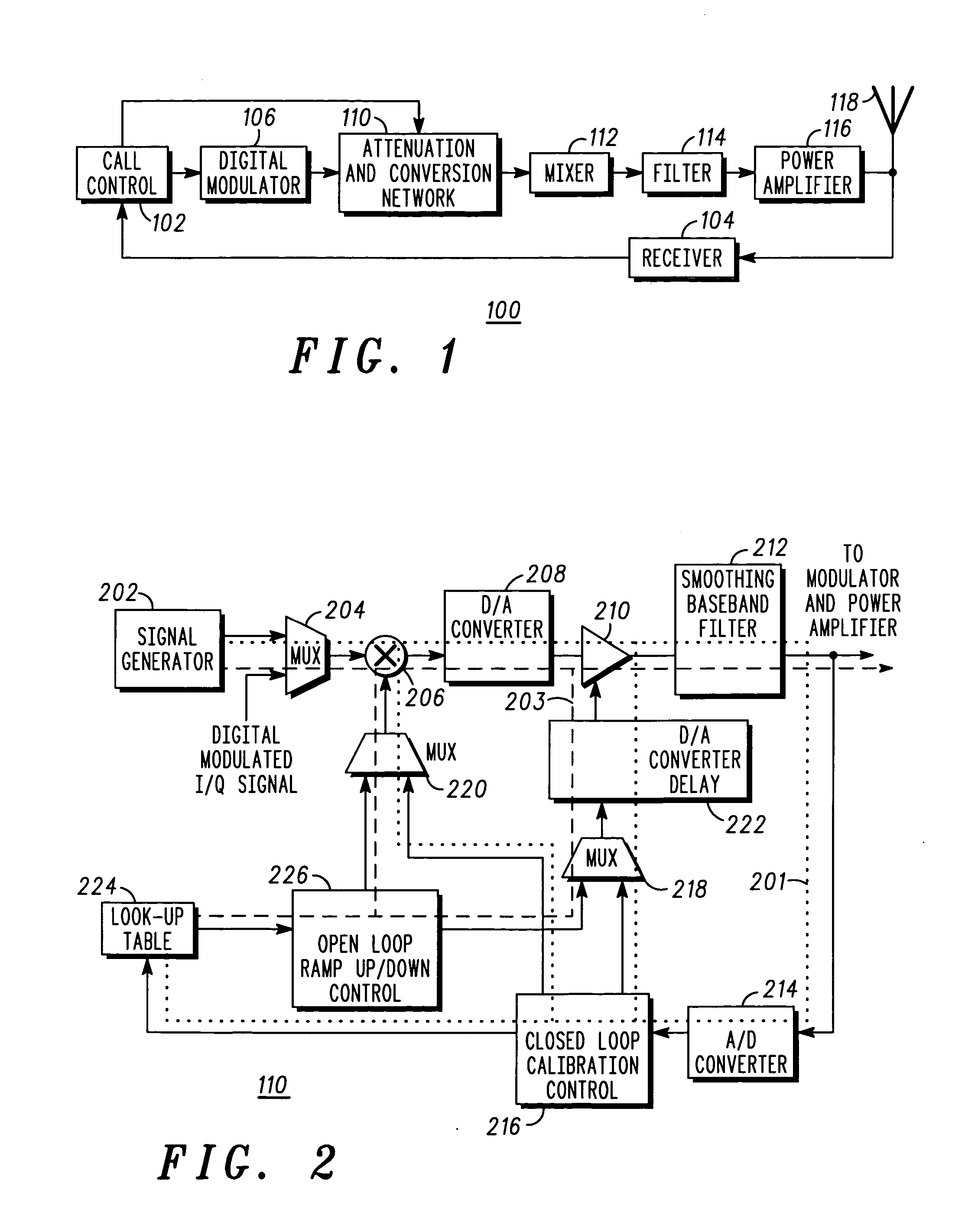
[0022] Referring now to FIG. 1, a block diagram of a transmitter 100 incorporating the self calibrating attenuator is shown. The transmitter includes call control block 102. Call control block 102 provides control of the remainder of the transmitter, provides the digital information transmitted by the radio, interprets signaling information from receiver 104 such as power control signals, and generates signaling information for the transmitter. The digital information from call control block 102 is passed into digital modulator 106 where the digital information is transformed into a digital baseband signal. Digital baseband signal is input into attenuation and conversion block 110 where the level of digital baseband signal is decreased by some predetermined value and the signal is converted from a digital to an analog signal and filtered to limit the spectral content of the analog signal. Attenuation and conversion block 110 is also coupled to control block 102 which allows control,...


PUM


Abstract

A method and system controls transmit power by combining the advantages of digital attenuation and analog baseband step attenuators by calibration to overcome the limitations of analog step attenuators. The calibration technique uses highly accurate digital attenuators to determine the actual sizes of the analog steps as analog step attenuator is stepped through a range of attenuation levels. A method of calibration accurately measures attenuation steps comparison to a digital attenuator so that the attenuation actually realized by the analog step attenuator is accurately known. Therefore, the difference between the attenuation realized by the analog step attenuator and the desired attenuation is accurately known. The difference is realized in the digital attenuator and the attenuation resulting from the composite of the digital and analog step attenuator can very accurately realize the requested attenuation.

Description

FIELD OF THE INVENTION [0001] This invention pertains to wireless technologies, and more particularly, to control the power radiated by a radio frequency transmitter. BACKGROUND OF THE INVENTION [0002] Cellular communications systems often require that the radiated power from the transmitter be tightly controlled. Controlling the transmit power levels has several advantages. First, control allows minimizing the transmitted power which allows the overall power consumed by the cellular radio can be reduced. This reduction extends battery life which is an important metric in design of cellular handsets. Power control is also required for closed loop power control between the base station and the mobile device for system functionality in Code Division Multiple Access (CDMA) systems, as necessitated by the protocol used. [0003] Controlling the transmitted power also has the affect of reducing the interference level in a cellular system. Often the total number of users in a cellular syste...

Claims


Application Information

Patent Timeline
Patent Type & Authority Applications(United States)
IPC IPC(8): H03C1/62H04B1/04H04B7/005H04B17/00
CPCH04W52/52H04B2001/0416
Inventor TALWALKAR, SUMIT A.RAHMAN, MAHIBURHOGGARTH, STEVEN P.
Owner APPLE INC
Learn More