Transmission apparatus
a technology of transmission apparatus and transmission shaft, which is applied in the direction of rotary clutches, fluid couplings, gearings, etc., can solve the problems of limited maximum transmission power and service life, difficult to apply toroidal-type cvt to a large equipment, and difficult to reduce the service life of toroidal-type cvt, which utilizes solid friction, etc., to achieve efficient transmission and increase the service life and power transmission limit
- Summary
- Abstract
- Description
- Claims
- Application Information
AI Technical Summary
Benefits of technology
Problems solved by technology
Method used
Image
Examples
first embodiment
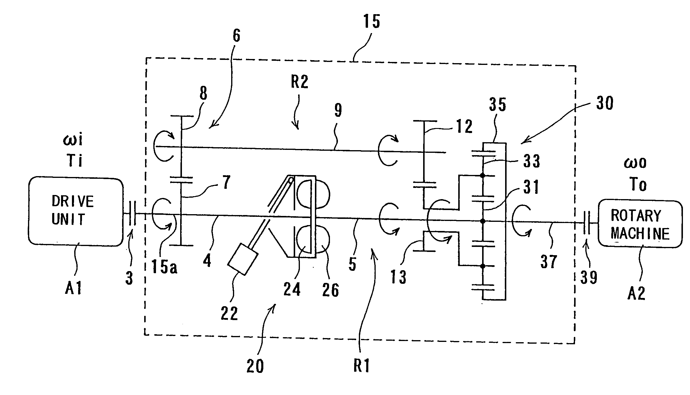
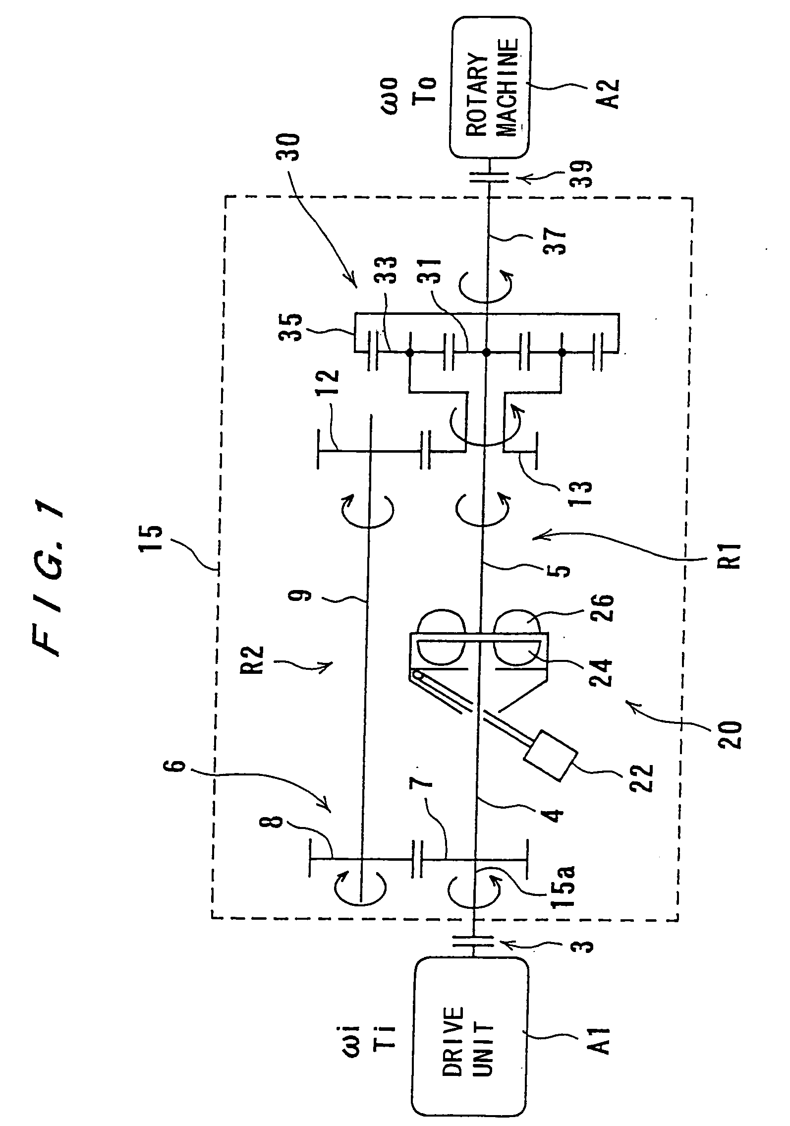
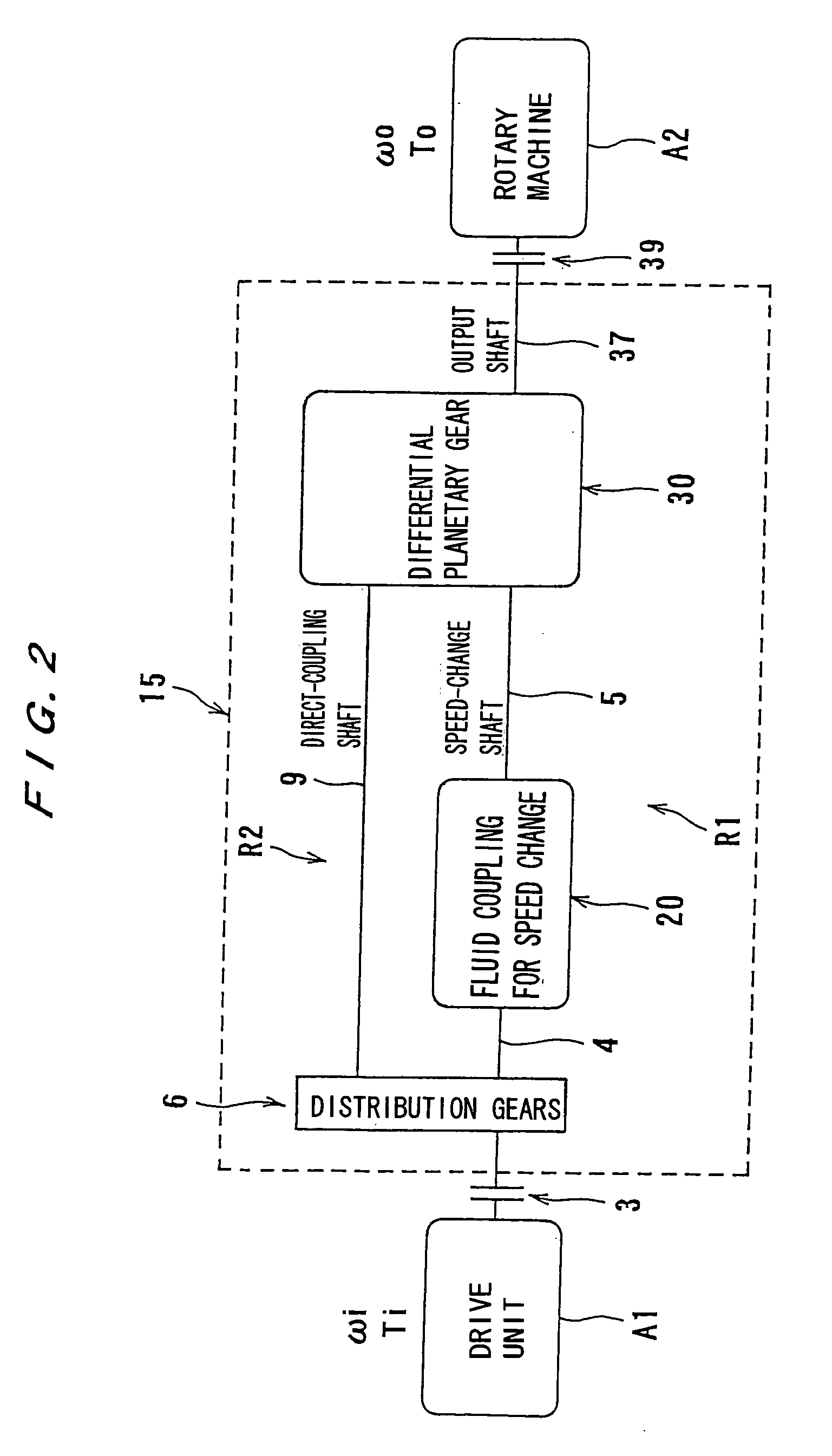
[0059]FIGS. 1 and 2 show the present invention. FIG. 1 is a schematic view showing a detailed structure of a transmission apparatus of the present invention, and FIG. 2 is a block diagram schematically showing the transmission apparatus. Those parts which are denoted by the same reference numerals as those of the conventional apparatus shown FIG. 23 have identical structure and function.
[0060] In FIGS. 1 and 2, a transmission apparatus 15 is disposed between a motor A1 (expressed as a drive unit A1 in FIG. 1) serving as a drive source and a fluid machinery A2 (expressed as a rotary machine A2 in FIG. 1) serving as a driven unit. The transmission apparatus 15 is coupled to the motor A1 and the fluid machinery A2 via an input-side clutch 3 and an output-side clutch 39.
[0061] The transmission apparatus 15 comprises a power-dividing unit 6, a fluid coupling 20 for speed change, and a differential planetary gear unit 30, each of which serves as an essential part thereof.
[0062] The powe...
eighth embodiment
[0158]FIG. 12 shows an In FIG. 12, an output shaft 60 of a drive unit, e.g., an electric motor M, is coupled to a first gear 61 constituting a dividing unit 6. The first gear 61 is in mesh with a second gear 62 of the dividing unit 6.
[0159] The dividing unit 6 has a first output shaft 63 serving as a rotating shaft of the first gear 61. This first output shaft 63 is connected to a sun gear 64 of a second differential planetary gear unit P2. A carrier 66 of planetary gears 65 of the differential planetary gear unit P2 is coupled to a gear 67 meshing with a gear 68 that is coupled to an output shaft 69 of a small-capacity variable-speed motor 70. A ring gear 71 of the second differential planetary gear unit P2 is connected to an output shaft 72.
[0160] In this example shown in FIG. 12, the output shaft 60 of the drive unit M is connected to the sun gear 64 via the output shaft 63, and a rotational power of the variable-speed motor 70 is transmitted to the planetary gears 65. Although...
ninth embodiment
[0165]FIG. 13 shows the present invention. An output shaft 60 of a drive unit M is connected to a first rotating element of a first differential planetary gear unit P1, and is also connected to a second rotating element, which mainly transmits a power, of the first differential planetary gear unit P1. A first output shaft 81 is a direct-coupling shaft and is connected to a second gear 82 of a converging unit 6B. A second output shaft 83, which is connected to a third rotating element of the first differential planetary gear unit P1, is a speed-change shaft and is connected to a first rotating element of the second differential planetary gear unit P2.
[0166] A second rotating element of this second differential planetary gear unit P2 is connected to an output shaft 69 serving as a motor shaft of a small-capacity variable-speed motor 70. Further, a third rotating element of the second differential planetary gear unit P2 is connected to a first gear 84 meshing with the second gear 82 of...
PUM
 Abstract
Description
Claims
Application Information
 - R&D
- Intellectual Property
- Life Sciences
- Materials
- Tech Scout
- Unparalleled Data Quality
- Higher Quality Content
- 60% Fewer Hallucinations
Browse by: Latest US Patents, China's latest patents, Technical Efficacy Thesaurus, Application Domain, Technology Topic, Popular Technical Reports.
© 2025 PatSnap. All rights reserved.Legal|Privacy policy|Modern Slavery Act Transparency Statement|Sitemap|About US| Contact US: help@patsnap.com


