
Method of manufacturing a semiconductor device and a semiconductor device

a manufacturing method and semiconductor technology, applied in semiconductor devices, semiconductor/solid-state device details, electrical equipment, etc., can solve the problems of high manufacturing cost of semiconductor devices, inability to achieve a further improvement of reliability, and difficulty in applying csp technique to products for which high reliability is required, so as to facilitate the removal of resin packages, prevent creasing of sheets, and high versatility

Inactive Publication Date: 2005-06-16
RENESAS SEMICON PACKAGE & TEST SOLUTIONS +1
View PDF15 Cites 27 Cited by
  • Summary
  • Abstract
  • Description
  • Claims
  • Application Information

AI Technical Summary

Benefits of technology

[0008] It is an object of the present invention to provide a technique capable of improving the reliability of a semiconductor device.
[0009] It is another object of the present invention to provide a technique capable of reducing the cost of a semiconductor device.

Problems solved by technology

However, the present inventor has found out that the following problems are involved in the above CSP technique using an insulating tape as a package substrate.
The problem is that it is difficult to apply the CSP technique to products for which high reliability is required.
For example, this is because in the CSP structure using an insulating tape as a package substrate it is inevitably required that the temperature cyclicity after packaging be set lower than the user's request, which may be attributable to the material of the package substrate being polyimide, thus making it impossible to attain a further improvement of reliability.
The second problem is that the semiconductor device manufacturing cost is high.
For example, this is because the polyimide tape as the material of the package substrate is expensive.
Another reason is that in the manufacture of a CSP using an insulating tape as a package substrate, each individual semiconductor chip is sealed and that therefore the number of products obtained per unit area is small, thus leading to a high basic unit price.

Method used


Image

  • Method of manufacturing a semiconductor device and a semiconductor device
  • Method of manufacturing a semiconductor device and a semiconductor device
  • Method of manufacturing a semiconductor device and a semiconductor device

Examples


first embodiment

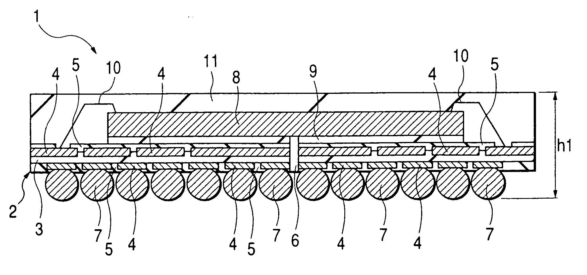
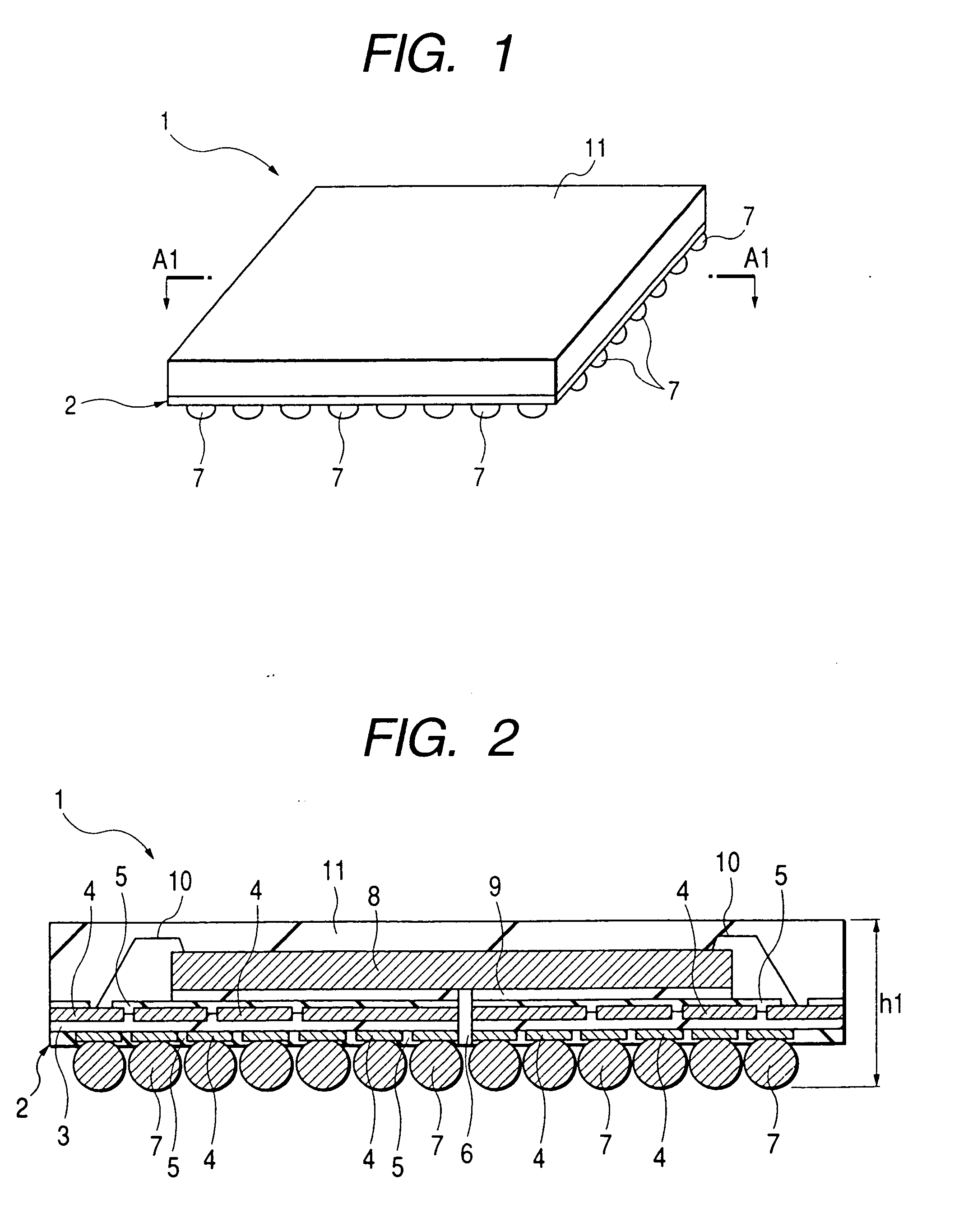
[0075]FIG. 1 is a perspective view of a semiconductor device embodying the present invention and FIG. 2 is a sectional view taken on line A1-A1 in FIG. 1.

[0076] The semiconductor device of this embodiment, indicated at 1, has, for example, an FBGA (Fine Pitch Ball Grid Array) structure. A package substrate 2 of the semiconductor device 1 is formed, for example, by a thin plate which is square in plan. The package substrate 2 comprises a substrate body 3, conductor patterns 4 and solder resist 5 both formed on a main surface (chip mounting surface) of the substrate body 3 and a back side (package mounting surface) thereof, a vent hole formed through both main surface and back side of the package substrate 2, and bump electrodes 7 bonded to the conductor patters 4 formed on the back side of the package substrate 2.

[0077] In this embodiment, as the material of the substrate 3 there is used a single-layer plate of a glass-epoxy resin equivalent to FR-5 which is high in heat resistance...

second embodiment

[0133] In this second embodiment another example of a semiconductor device manufacturing method according to the present invention will be described. FIGS. 32 and 33 illustrate a state in which the strip substrate 12 has been conveyed to a mold 16, of which FIG. 33 is a sectional view of a plane perpendicular to FIG. 32.

[0134] In this embodiment, a laminate mechanism portion 25 is provided in a mold 16. The laminate mechanism portion 25 comprises a laminate film 25a and reels 25b for taking up the laminate film. The laminate film 25a is an insulating film of a high heat resistance having a size capable of covering approximately the whole of an inner wall surface of each cavity 16c of an upper mold 16b2. The laminate film 25a is interposed between a lower mold half 16a2 and the upper mold half 16b2 of the mold 16.

[0135] In this embodiment, vacuum suction holes are not formed in the lower mold half 16a2 of the mold 16. Other structural points of the lower mold half are the same as i...

third embodiment

[0141] In this third embodiment a further example of a semiconductor manufacturing method according to the present invention will be described. FIG. 38 shows a state in which the strip substrate 12 has been conveyed to a mold 16.

[0142] In this third embodiment, the laminate mechanism portion 25 described in the above second embodiment is provided in the mold 16. The structure of a lower mold half 16a of the mold 16 is the same as that described in the previous first embodiment. That is, plural vacuum suction holes 17 are formed in the lower mold half 16a in the same arrangement as in the first embodiment. As to the structure of an upper mold half 16b2 used in this embodiment, it is the same as that used in the second embodiment. That is, plural vacuum suction holes 26 are also formed in the upper mold half 16b2 in the same arrangement as in the second embodiment.

[0143] First, as shown in FIG. 39, the strip substrate 12 is placed on a molding surface of the lower mold half 16a of t...


PUM

PropertyMeasurementUnit
diameteraaaaaaaaaa
thicknessesaaaaaaaaaa
diameteraaaaaaaaaa

Abstract

The back side of a strip substrate with plural semiconductor chips mounted thereon is vacuum-chucked to a lower mold half of a mold, and in this state the plural semiconductor chips are sealed with resin simultaneously to form a seal member. Thereafter, the strip substrate and the seal member are released from the mold and are cut into plural semiconductor devices. The semiconductor devices thus obtained are improved in their mounting reliability.

Description

BACKGROUND OF THE INVENTION [0001] The present invention relates to a semiconductor device manufacturing method and a semiconductor technique. Particularly, the invention is concerned with a technique which is effective in its application to a semiconductor device having a small-sized package structure. [0002] A CSP (Chip Size Package) or the like having an external package size almost equal to or slightly larger than that of a semiconductor chip permits a high-density packaging corresponding to bare chip packaging and is relatively low in its manufacturing cost. With these advantages, there is now an increasing demand for CSP in the field of small-sized, light-weight electronic devices such as portable information devices, digital cameras, and notebook type personal computers. [0003] In connection with the CSP, various package forms are available. But there generally is adopted a Ball Grip Array (BGA) structure wherein solder bumps are attached to one side of a package substrate wi...

Claims


Application Information

Patent Timeline
Patent Type & Authority Applications(United States)
IPC IPC(8): B29C45/14H01L21/56H01L23/00H01L23/12H01L23/31H01L23/498
CPCH01L21/561H01L2924/07802H01L23/3128H01L23/49816H01L23/49838H01L23/564H01L24/45H01L24/97H01L2223/5442H01L2223/54473H01L2224/16H01L2224/32225H01L2224/45015H01L2224/45144H01L2224/48227H01L2224/48228H01L2224/73265H01L2224/92H01L2224/97H01L2924/01002H01L2924/01004H01L2924/01029H01L2924/01033H01L2924/01047H01L2924/0105H01L2924/01078H01L2924/01079H01L2924/01082H01L2924/0781H01L2924/14H01L2924/1433H01L2924/15151H01L2924/15311H01L2924/20752H01L2924/30105H01L21/565H01L2224/48091H01L2924/01028H01L2924/01087H01L2924/01023H01L2924/01006H01L2924/01005H01L24/48H01L2224/83H01L2224/85H01L2924/00014H01L2224/92247H01L2924/00H01L2924/00012H01L24/73H01L2924/181H01L2924/351H01L21/56
Inventor TAKAHASHI, NORIYUKISUZUKI, MASAYUKITSUCHIYA, KOUJIMATSUURA, TAKAOHASHIZUME, TAKANORIICHITANI, MASAHIROSUZUKI, KAZUNARINISHITA, TAKAFUMIIMURA, KENICHIMIWA, TAKASHI
Owner RENESAS SEMICON PACKAGE & TEST SOLUTIONS
Learn More