Organic element for electroluminescent devices
a technology of electroluminescent devices and organic elements, which is applied in the direction of discharge tube/lamp details, indium organic compounds, natural mineral layered products, etc., can solve the problems of large loss of efficiency and performance limitations, and hinder many desirable applications
- Summary
- Abstract
- Description
- Claims
- Application Information
AI Technical Summary
Problems solved by technology
Method used
Image

Examples
synthetic example 1
Preparation of Ligands
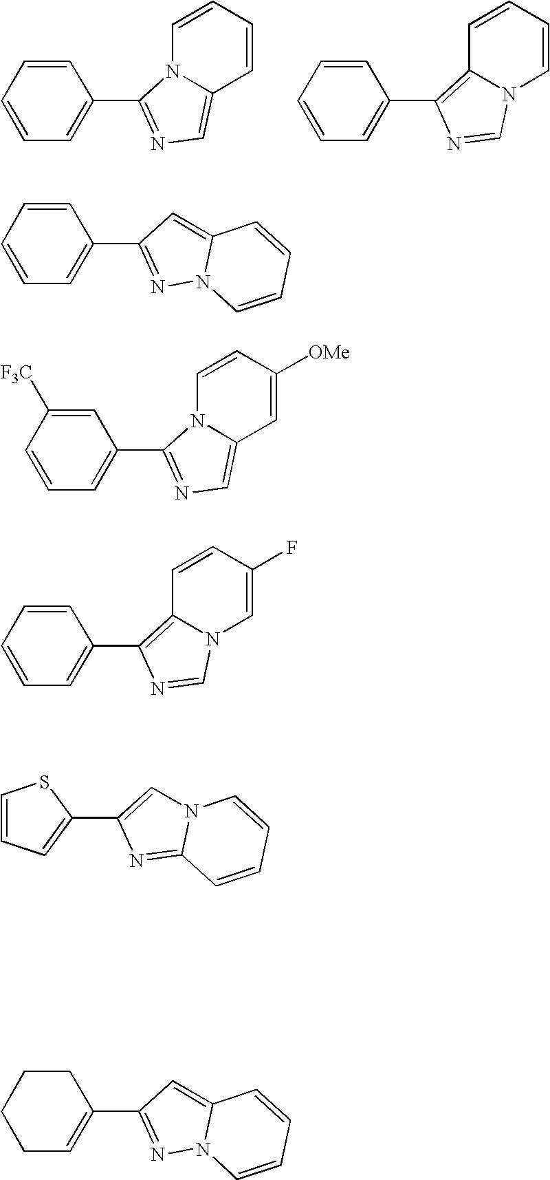
[0169] 2-Phenylimidazo[1,2-a]pyridine was prepared by the following procedure. A solution of 2-aminopyridine (9.4 g, 0.1 mol) and bromoacetophenone (19.9 g, 0.1 mol) in ethanol (75 mL) was heated to reflux for 2 h. The ethanol was removed in vacuo and the residue redissolved in 100 mL ethyl acetate. The solution was washed with 1N NaHCO3 (50 mL), followed by a water wash. The organics were dried over magnesium sulfate, filtered and the solvent removed in vacuo. Chromatography on silica with dichloromethane / ethyl acetate (90 / 10) eluent yielded the 2-phenylimidazo[1,2-a]pyridine in 88% yield, mp 134° C. 1H NMR and mass spectra analysis confirmed the structure.
[0170] 2-Phenylpyrazolo[1,5-a]pyridine was prepared by the following procedure. A solution of 2-(phenylethynyl)pyridine (3.2 g, 0.018 mol) in dichloromethane (20 mL) was cooled to 0° C. in an ice bath. A solution of O-mesitylenesulfonylhydroxylamine in dichloromethane was added dropwise, keeping the temper...
synthetic example 2
Preparation of Bis(2-phenylimidazo[1,2-a]pyridinato-N,C)iridium(III)(acetylacetate) (Inv-24)
[0171] K3IrBr6 (2.75 g) and 2-phenylimidazo[1,2-a]pyridine (1.69 g) were placed in a 125 mL round-bottom flask. 2-Ethoxy ethanol (45 mL) and deionized water (15 mL) were added. The mixture was freeze-thaw degassed and refluxed 4 hrs under nitrogen atmosphere. After cooling, the resulting precipitate was filtered in air and washed with ethanol and water to give 1.975 g of yellow-brown powder. The mass spectrum was consistent with the formulation terakis(2-phenylimidazo[1,2-a]pyridinato)(di-μ-bromo)diiridium(III). This material was used in the next step without further purification.
[0172] Tetrakis(2-phenylimidazo[1,2-a]pyridinato)(di-μ-bromo)diiridium(III) (0.654 g) and sodium acetylacetonate hydrate (0.417 g) were placed in a 100 mL round bottom flask. 1,2-Dichloroethane (30 mL) was added. The mixture was freeze-thaw degassed and then refluxed under nitrogen 20 h. After cooling, the reaction...
example 1
DEVICE EXAMPLE 1
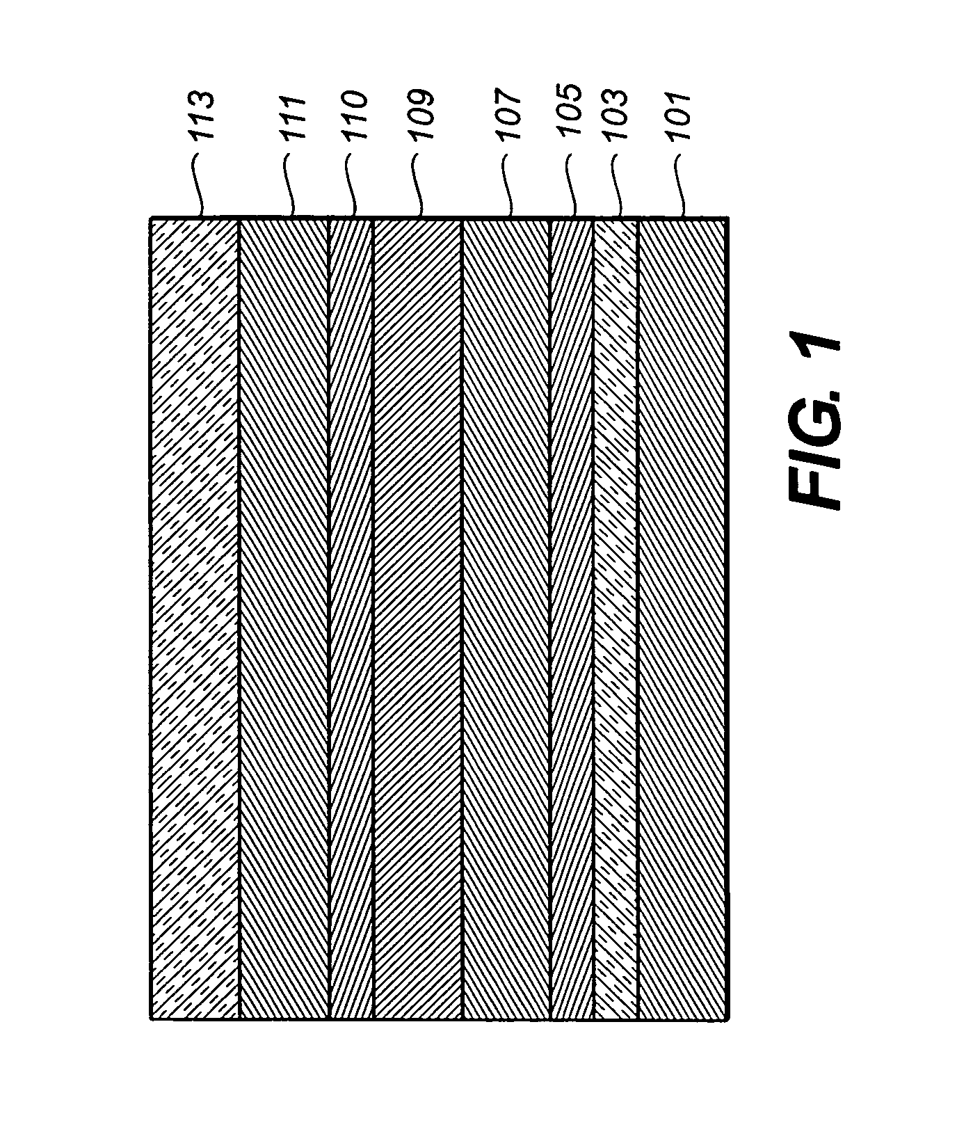
[0173] An EL device (Device 1) satisfying the requirements of the invention was constructed in the following manner:
[0174] A glass substrate coated with an 85-nm layer of indium-tin oxide (ITO) as the anode was sequentially ultrasonicated in a commercial detergent, rinsed in deionized water, degreased in toluene vapor and exposed to ultraviolet and ozone for several minutes. [0175] 1. A glass substrate coated with an 85-nm layer of indium-tin oxide (ITO) as the anode was sequentially ultrasonicated in a commercial detergent, rinsed in deionized water, degreased in toluene vapor and exposed to ultraviolet and ozone for several minutes. [0176] 2. Over the ITO was deposited a 60-nm PEDOT hole-injecting layer (HIL) by spin coating an aqueous solution of PEDOT / PSS (1.3% in water, Baytron® P fromH. C. Stark, Inc.) under controlled spinning rate of 1750 rpm to obtain the desired layer thickness of about 60 nm and then annealing the coating on a heated metal block in air at...
PUM
| Property | Measurement | Unit |
|---|---|---|
| wt % | aaaaa | aaaaa |
| thick | aaaaa | aaaaa |
| thickness | aaaaa | aaaaa |
Abstract
Description
Claims
Application Information
 - R&D
- Intellectual Property
- Life Sciences
- Materials
- Tech Scout
- Unparalleled Data Quality
- Higher Quality Content
- 60% Fewer Hallucinations
Browse by: Latest US Patents, China's latest patents, Technical Efficacy Thesaurus, Application Domain, Technology Topic, Popular Technical Reports.
© 2025 PatSnap. All rights reserved.Legal|Privacy policy|Modern Slavery Act Transparency Statement|Sitemap|About US| Contact US: help@patsnap.com