
Powder compaction press and method for manufacturing of capacitor anodes

a technology of capacitor anodes and compaction presses, which is applied in the manufacture of capacitors, variable capacitors, manufacturing tools, etc., can solve the problems of capacitor elements being damaged, the compaction device typically does not produce uniformly compacted capacitor elements,

Active Publication Date: 2005-06-09
KEMET ELECTRONICS CORP
View PDF12 Cites 8 Cited by
  • Summary
  • Abstract
  • Description
  • Claims
  • Application Information

AI Technical Summary

Benefits of technology

The invention is about making a capacitor with an irregular surface by compacting valve powder evenly throughout the element. The method uses a powder compaction press that doesn't damage the capacitor and ensures uniform compaction. The capacitor is formed using interleaved rib and channel punches that compress the powder equally throughout the element. The channel punches are withdrawn first to avoid friction destruction of the element. The technical effect is the creation of a reliable and efficient capacitor with a uniform surface.

Problems solved by technology

However when the capacitor element has an irregular exterior surface the compaction device typically does not produce a uniformly compacted capacitor element.
It has also been found that the capacitor element may be damaged by the withdrawal of the punches used in forming such an element.

Method used


Image

  • Powder compaction press and method for manufacturing of capacitor anodes
  • Powder compaction press and method for manufacturing of capacitor anodes
  • Powder compaction press and method for manufacturing of capacitor anodes

Examples


Embodiment Construction

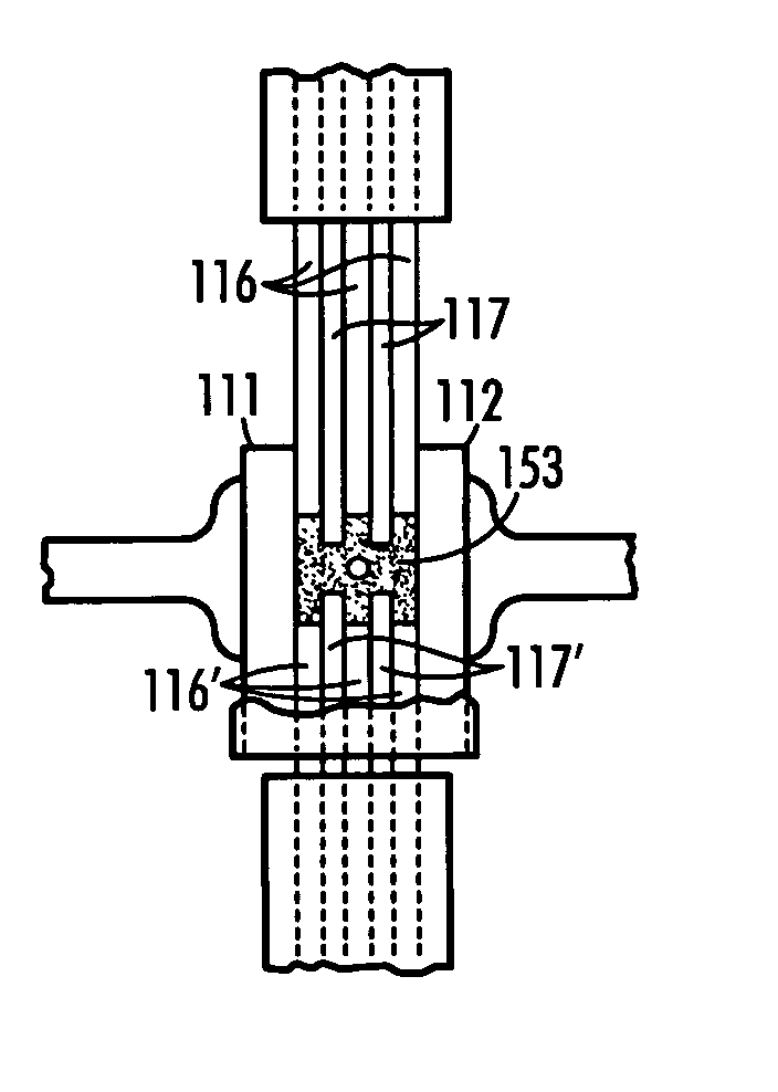
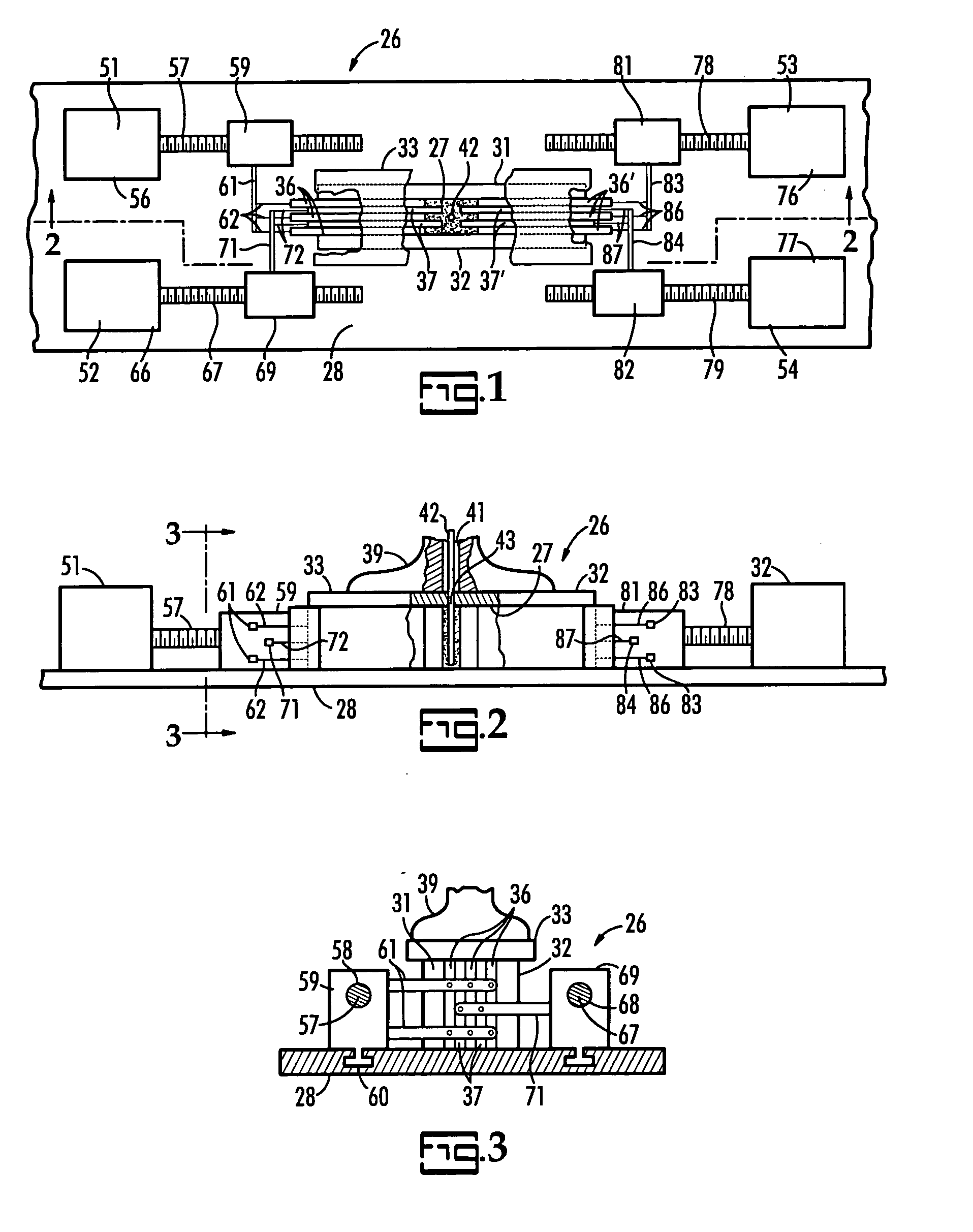
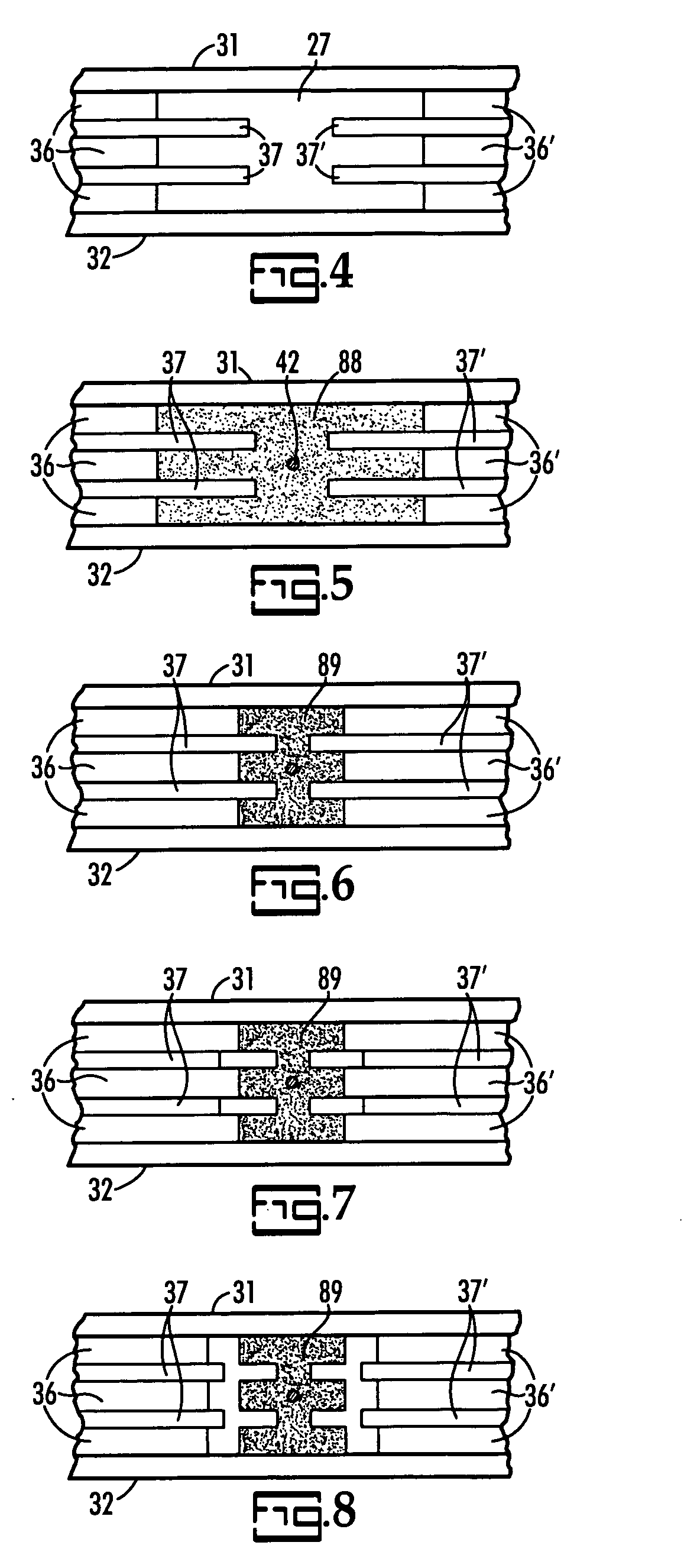
[0029] A horizontal powder press 26 is illustrated in FIGS. 1, 2 and 3. An elongated compression chamber 27 of uniform quadrilateral cross section is formed by a bottom wall in the form of flat support 28, a pair of parallel side walls 31, 32 having confronting parallel vertical surfaces of equal height extending upwardly from the upwardly facing surface of the support 28 and a top wall 33 having a flat bottom surface in engagement with the coplanar top surfaces of the side walls 31, 32. A set of six opposed rib punches 36, 36′ and a set of four opposed channel punches 37, 37′ extend into opposite open ends of the compression chamber 27. The linearly reciprocable rib punches 36 and channel punches 37 are interleaved flat plates. The top wall 33 is held in place on the top surface of the side walls 31, 32 by a press foot 39 which has a vertically extending opening 41 for accommodating a wire 42 inserted through an opening 43 in the top wall 33 and into the powder compression chamber ...


PUM

PropertyMeasurementUnit
distanceaaaaaaaaaa
speedaaaaaaaaaa
linear distanceaaaaaaaaaa

Abstract

A powder compaction press having opposed rib and channel punches which are interleaved and a production method are used to produce capacitor elements having a uniform compaction density and which are free of surface imperfections.

Description

TECHNICAL FIELD [0001] This invention relates to a powder compaction press and a method for making capacitor anodes. BACKGROUND OF THE INVENTION [0002] Compaction of tantalum or valve powder to make capacitor elements is known in the art as evidenced by the disclosure of U.S. Pat. No. 5,949,639 issued Sep. 7, 1999 to T. Malda et al. for a Capacitor Element for Solid Electrolytic Capacitor, Device and Process for Making the Same and by the disclosure of U.S. Pat. No. 6,191,936 issued Feb. 20, 2001 to D. A. Webber et al. for a Capacitor Having Textured Pellet and Method for Making Same. [0003] When making capacitor anodes by compaction of valve powder it is desired to have uniform compaction. However when the capacitor element has an irregular exterior surface the compaction device typically does not produce a uniformly compacted capacitor element. It has also been found that the capacitor element may be damaged by the withdrawal of the punches used in forming such an element. SUMMARY...

Claims


Application Information

Patent Timeline
Patent Type & Authority Applications(United States)
IPC IPC(8): B22F3/00B22F3/03H01G9/00H01G9/052H01G9/15H01G13/00
CPCB22F3/03H01G9/052H01G9/15Y10T29/42Y10T29/53122Y10T29/435Y10T29/5313Y10T29/5317Y10T29/417Y10T29/43B30B11/007B30B11/027B30B11/34H01G13/00
Inventor POLTORAK, JEFFREY P.
Owner KEMET ELECTRONICS CORP
Learn More