
Wire stranding apparatus and method for manufacturing stranded wire

a technology of stranding apparatus and manufacturing method, which is applied in the direction of cable/conductor manufacturing, continuous wounding machine, control, etc., can solve the problems of constant change of the tension of the wires to be wound on the core wire, and it is difficult to obtain a stranded wire having a uniform degree of stranding, so as to increase the manufacturing speed of the obtained stranded wire

Active Publication Date: 2021-10-26
NITTOKU CO LTD
View PDF49 Cites 0 Cited by
  • Summary
  • Abstract
  • Description
  • Claims
  • Application Information

AI Technical Summary

Benefits of technology

[0008]The present invention aims to provide a wire stranding apparatus and a method for manufacturing a stranded wire which can increase a manufacturing speed of a stranded wire while making a degree of stranding uniform.

Problems solved by technology

However, if the speed of the spools revolving about the core wire is increased, an inconvenience is that a centrifugal force acts on the wires fed from the spool and extending along the core wire and tensions exceeding the predetermined tension applied by the tension device are applied to the wires by the centrifugal force.
If the revolving speed of the spools about the core wire is increased to increase the manufacturing speed of the stranded wire, a situation occurs in which the tensions of the wires to be wound on the core wire constantly change.
If the tensions of the wires change, lengths of the wires to be spirally wound on the core wire per unit length also change and it becomes difficult to obtain a stranded wire having a uniform degree of stranding.

Method used


Image

  • Wire stranding apparatus and method for manufacturing stranded wire
  • Wire stranding apparatus and method for manufacturing stranded wire
  • Wire stranding apparatus and method for manufacturing stranded wire

Examples


Embodiment Construction

[0017]Hereinafter, an embodiment is described with reference to the drawings.

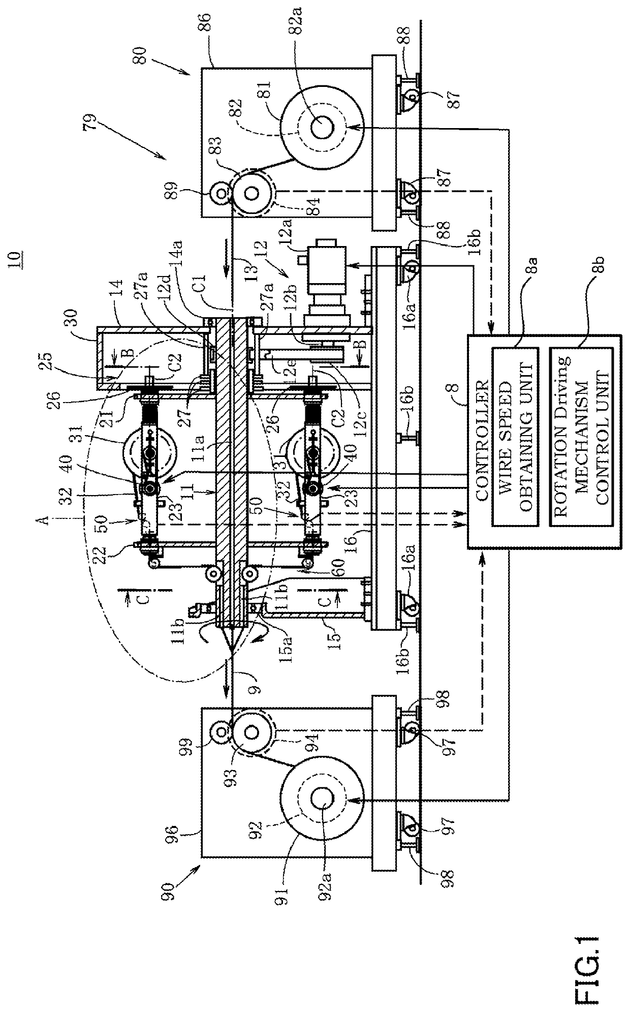
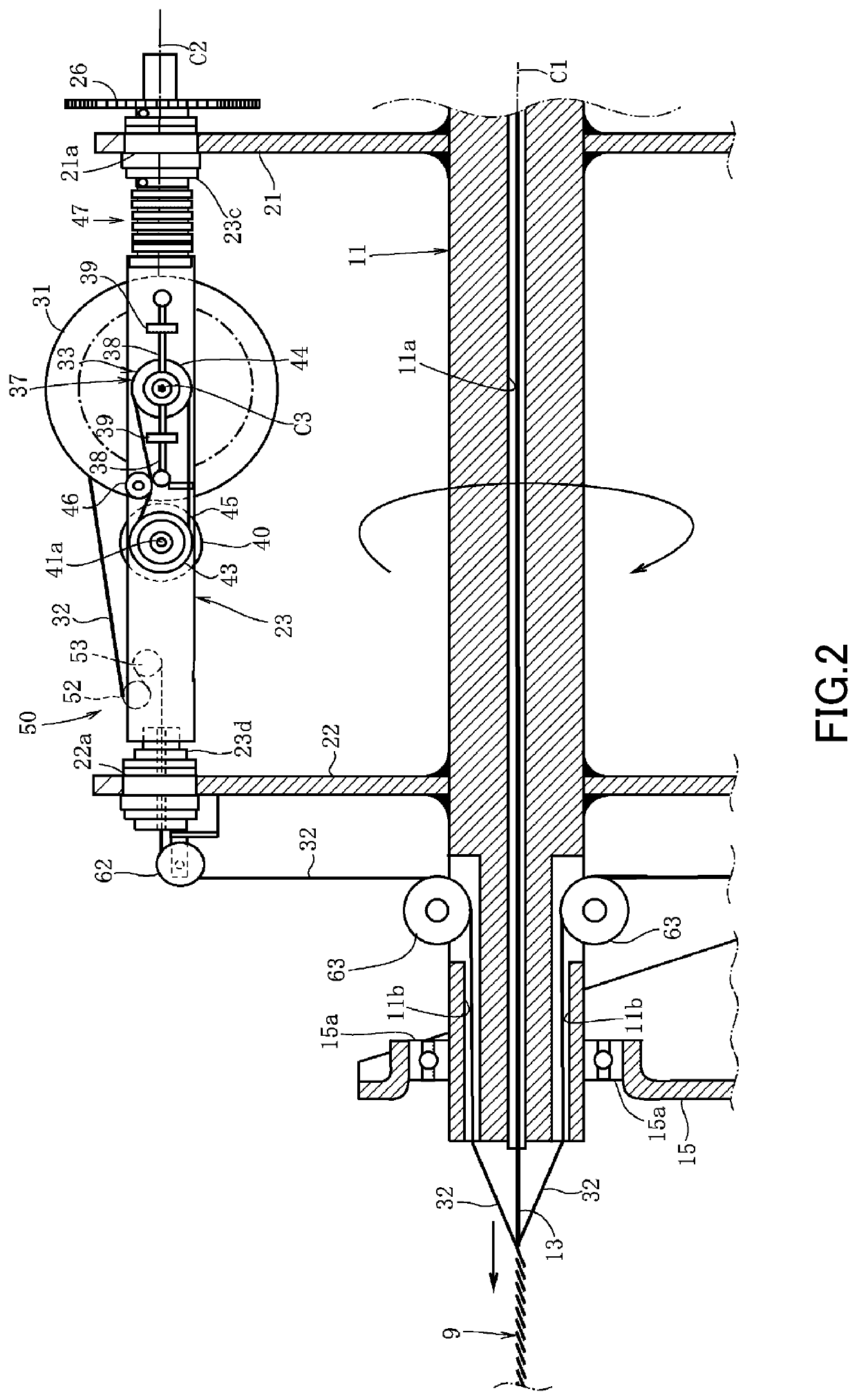
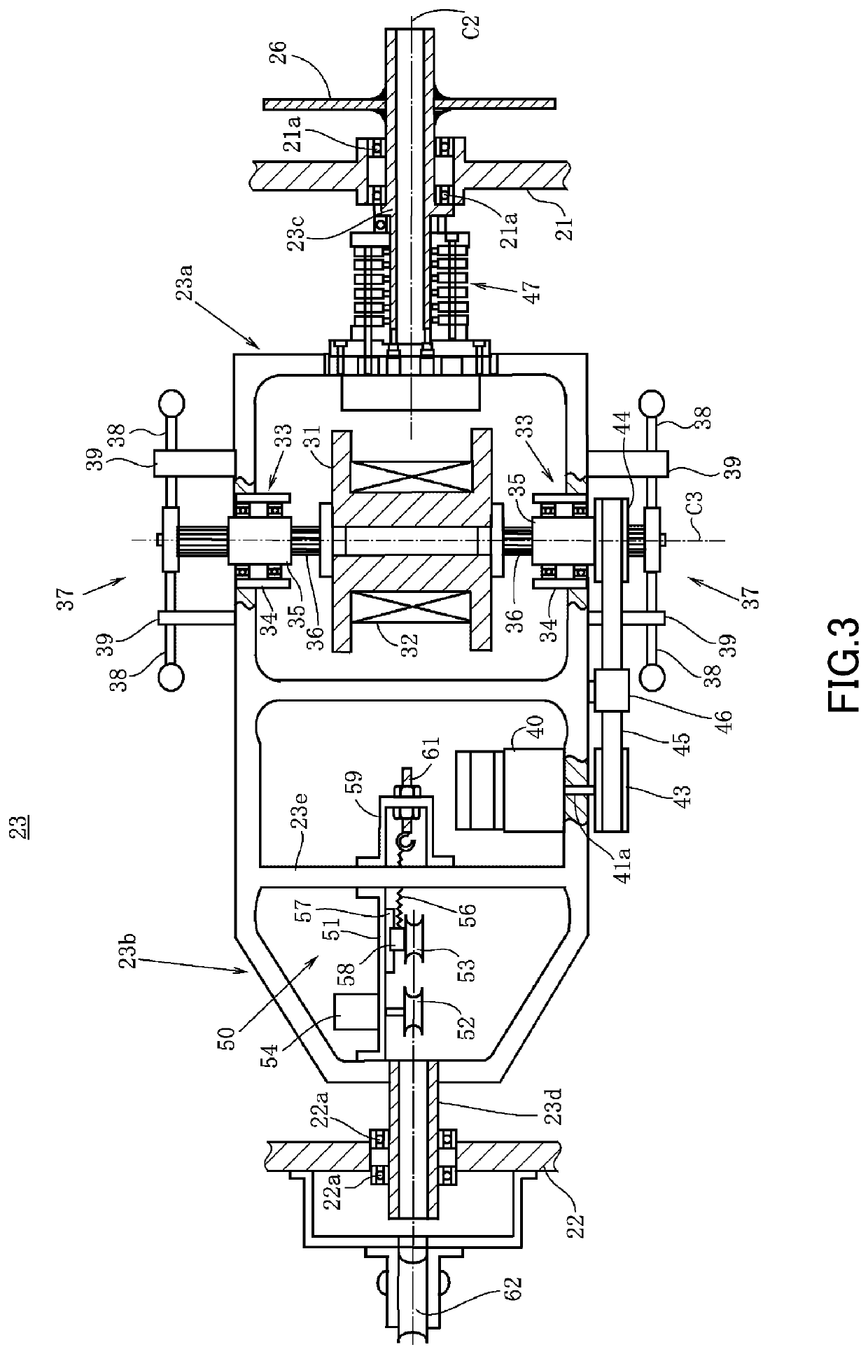
[0018]A wire stranding apparatus 10 according to the present embodiment is shown in FIG. 1. The wire stranding apparatus 10 is controlled by a controller 8 serving as a control device to be described later and includes a revolving mechanism 12 configured to revolve spools 31 about a core wire 13 extending straight. In the present embodiment, the core wire 13 is provided through a center of a shaft member 11, and the revolving mechanism 12 includes the shaft member 11.

[0019]The shaft member 11 is a rod-like member having a circular cross-section, and a core wire passage 11a through which the core wire 13 passes is formed along a center axis of the shaft member 11. Specifically, the shaft member 11 is a tubular member (specifically, hollow cylindrical member) provided to linearly extend, and the core wire passage 11a through which the core wire 13 passes is formed on an inner peripheral side of the shaft memb...


PUM

PropertyMeasurementUnit
speedaaaaaaaaaa
rotating speedaaaaaaaaaa
tensionaaaaaaaaaa

Abstract

A wire stranding apparatus, comprising: a core wire moving mechanism configured to move a core wire in an axial direction; a spool configured to feed a wound wire by rotation; a revolving mechanism configured to revolve the spool about the core wire; a rotation driving mechanism configured to feed the wire by rotating the spool, the wire fed from the spool being spirally wound on an outer periphery of the core wire moving in the axial direction by revolution of the spool; and a control device including a wire speed obtaining unit configured to obtain a speed of the wire to be wound on the core wire and a rotation driving mechanism control unit configured to control the rotation driving mechanism such that the speed of the wire obtained by the wire speed obtaining unit has a predetermined value.

Description

TECHNICAL FIELD[0001]The present invention relates to a wire stranding apparatus and a method for manufacturing a stranded wire.BACKGROUND ART[0002]JP2017-33815A discloses a wire stranding apparatus for spirally winding wires unwound and fed from spools around a core wire by revolving the spools having the wires wound and stored thereon around the core wire moving in an axial direction and turning (rotating) the spools.[0003]In this wire stranding apparatus, the wire unwound and fed from the spool extends along the core wire from the spool, has then a predetermined tension applied thereto by a tension device and is, thereafter, spirally wound around the core wire.SUMMARY OF INVENTION[0004]On the other hand, in such a conventional wire stranding apparatus, it is necessary to increase a revolving speed of the spools together with a moving speed of the core wire in order to increase a manufacturing speed of an obtained stranded wire.[0005]However, if the speed of the spools revolving a...

Claims


Application Information

Patent Timeline
Patent Type & Authority Patents(United States)
IPC IPC(8): D01H1/14
CPCD01H1/14B21F7/00H01B13/0214B21F17/00D07B3/06D07B7/022D07B2301/254D07B2301/3583D07B2301/55D07B2301/251D07B2207/4095
Inventor SHIBUYA, NAO
Owner NITTOKU CO LTD
Learn More