
Drying apparatus, and an inkjet printing apparatus having the same

a technology of inkjet printing and drying apparatus, which is applied in printing presses, other printing apparatus, printing, etc., can solve the problems of inability to dry web paper on the transport route, difference in the degree of dryness in the transverse direction of web paper, and inability to take the web paper off the transport route. , to achieve the effect of improving the quality of printing and reducing the area of passage sections

Active Publication Date: 2020-07-21
DAINIPPON SCREEN MTG CO LTD
View PDF5 Cites 0 Cited by
  • Summary
  • Abstract
  • Description
  • Claims
  • Application Information

AI Technical Summary

Benefits of technology

[0008]This invention has been made having regard to the state of the art noted above, and its object is to provide a drying apparatus which can make the degree of dryness substantially uniform in a transverse direction of web paper, and an inkjet printing apparatus having such a drying apparatus.
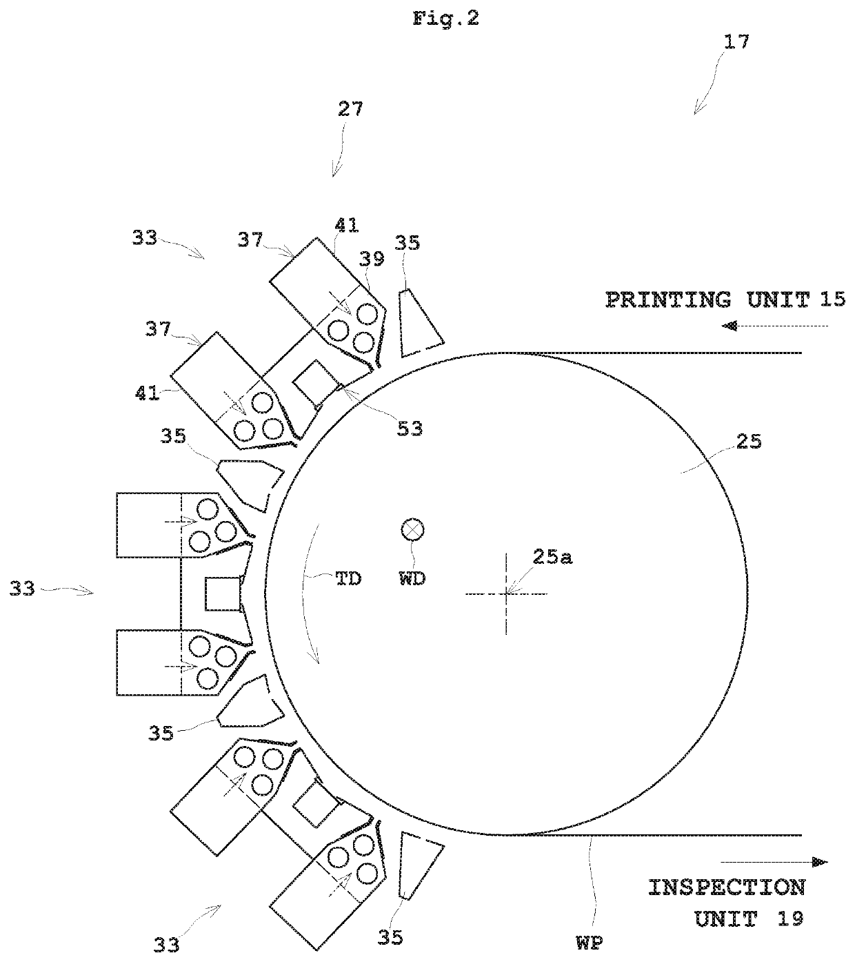
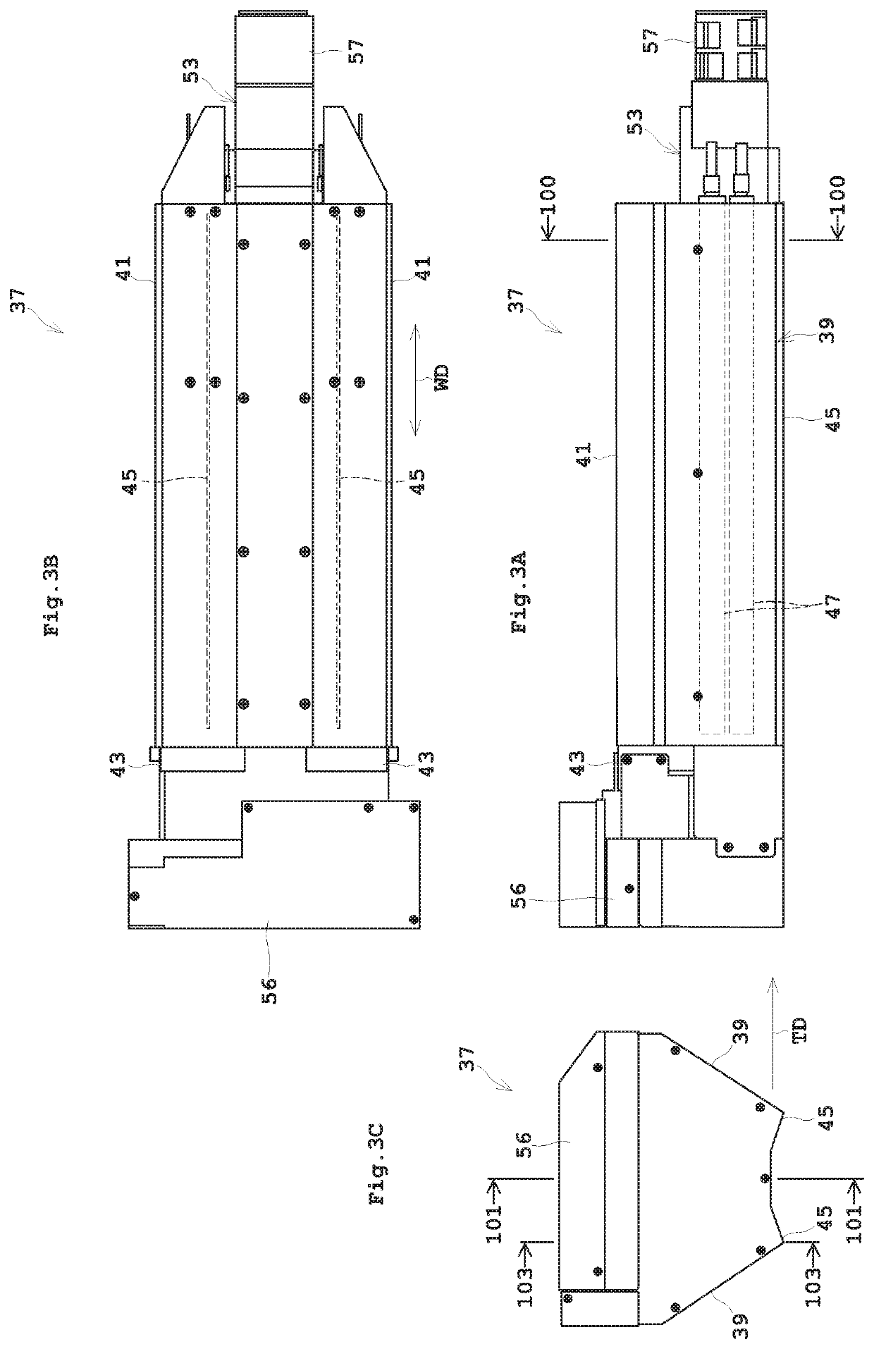
[0011]According to this invention, the warm air blasting unit includes one air intake duct disposed between a pair of warm air blasting portions and connected to one end of the fan duct of each warm air blasting portion. Consequently, since the one air intake duct recovers warm air, the passage sectional area can be made larger than in the prior art. As a result, the intake of warm air in the transverse direction of the printing medium can be made uniform. This can substantially uniform a temperature distribution on the transport route to which warm air is blown from the blasting ports of the nozzle cases. Consequently, the degree of dryness in the transverse direction of the printing medium can be made substantially uniform.
[0013]Air heat insulation is provided for each nozzle case and air intake duct by locating the air layer between the nozzle case and air intake duct. Consequently, the nozzle cases are not subject to influences of air colder than the warm air in the nozzle cases, the cold air being fed in by the suction fan from the other end of the air intake duct, thereby preventing a temperature drop in portions adjacent the suction fan of the nozzle cases. As a result, the temperature distribution in the transverse direction of the printing medium of the warm air blown off from the blasting ports of the nozzle cases can be made further uniform.
[0015]A plurality of air intake hoods are arranged adjacent the warm air intake ports of the suction fan, and the hoods have openings formed to have hood area percentage becoming smaller away from the suction fan along a logarithmic function. Consequently, flow path resistance, which is large adjacent the near the suction fan, becomes logarithmically smaller away from the suction fan. As a result, even when the quantity of airflow of the suction fan is adjusted, the air intake in the transverse direction perpendicular to the transport direction of the printing medium can be inhibited from being put out of balance, and variations in temperature distribution can be minimized. Thus, even if the quantity of warm air blown off from the blasting ports is changed according to characteristics of the printing medium, the degree of dryness in the transverse direction can be maintained constant.
[0019]Since, generally, flow speed lowers due to friction with the side plates adjacent the opposite ends relative to the opening length of the blasting port in the transverse direction, a length that provides a uniform flow speed is shorter than the opening length. So, by discharging part of the warm air from the spill holes in the side plates at the opposite ends of the blasting port, the friction causing pressure loss in the opposite end regions of the blasting port can be reduced. Consequently, the warm air having a nearly uniform flow speed can be blown off over the full width of the blasting port. The length that provides a uniform flow speed can be increased, thereby to inhibit the nozzle case from enlarging in the transverse direction. As a result, the nozzle case can be reduced in size, thereby to attain a reduction in size of the warm air blasting unit.
[0021]According to this invention, the warm air blasting unit includes one air intake duct disposed between a pair of warm air blasting portions and connected to one end of the fan duct of each warm air blasting portion. Consequently, since the one air intake duct recovers warm air, the passage sectional area can be made larger than in the prior art. As a result, the intake of warm air in the transverse direction of the printing medium can be made substantially uniform. This can substantially uniform a temperature distribution on the transport route to which warm air is blown from the blasting ports of the nozzle cases. Consequently, the degree of dryness in the transverse direction of the printing medium can be made substantially uniform, thereby improving the quality of printing by the printing unit.

Problems solved by technology

However, the conventional example with such construction has the following problem.
Consequently, compared with a side near the suction fan, a side far from the suction fan has a weak air intake, thus causing an uneven intake of the warm air in the transverse direction of the web paper.
As a result, there occurs a problem of a difference in the degree of dryness in the transverse direction of the web paper.
It is unrealizable to dry the web paper on the transport route uniformly in the transverse direction only by blowing warm air to provide an even temperature distribution in the transverse direction.

Method used


Image

  • Drying apparatus, and an inkjet printing apparatus having the same
  • Drying apparatus, and an inkjet printing apparatus having the same
  • Drying apparatus, and an inkjet printing apparatus having the same

Examples


Embodiment Construction

[0035]An embodiment of this invention will be described hereinafter with reference to the drawings.

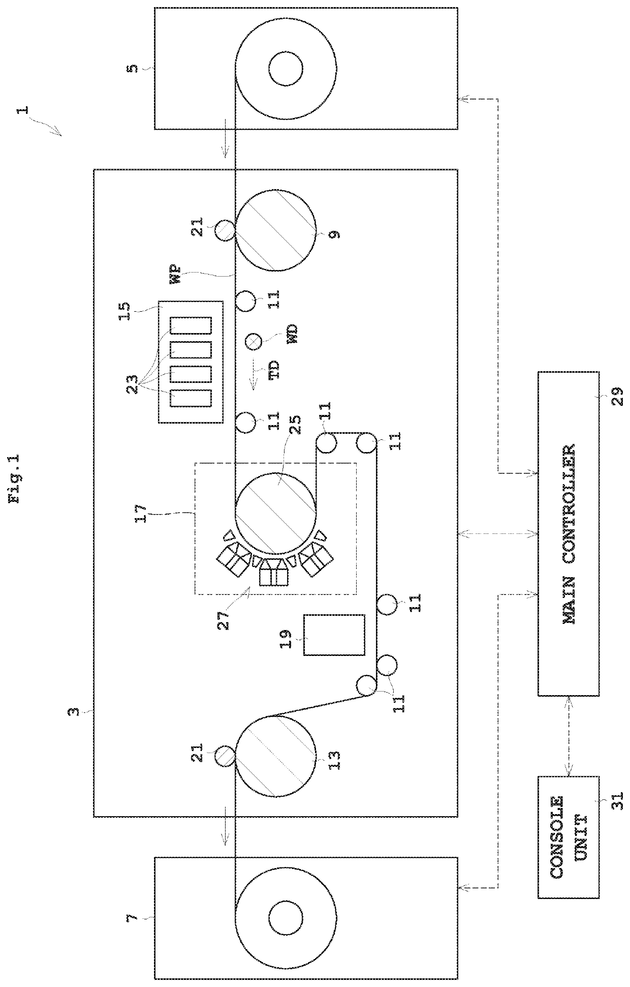
[0036]FIG. 1 is an outline schematic view showing an entire construction of an ink jet printing system according to the embodiment.

[0037]An ink jet printing system 1 includes an inkjet printing apparatus 3, a paper feeder 5, and a takeup roller 7. The inkjet printing apparatus 3 prints on sheetlike web paper WP. The paper feeder 5 holds a roll of web paper WP to be rotatable about a horizontal axis, and unwinds the web paper WP from the roll of web paper WP to feed it to the inkjet printing apparatus 3. The takeup roller 7 winds up the web paper WP printed in the inkjet printing apparatus 3 into a roll form around a horizontal axis. Regarding the supply side of web paper WP as upstream and the delivery side of web paper WP as downstream, the paper feeder 5 is located upstream of the inkjet printing apparatus 3, and the takeup roller 7 downstream of the inkjet printing apparatus 3.

[0038...


PUM


Abstract

A drying apparatus for drying a printing medium having ink droplets dispensed thereto includes a rotatable drive roller, and a warm air blasting unit. The warm air blasting unit includes a pair of warm air blasting portions, and one air intake duct. Each warm air blasting portion has a nozzle case, a fan duct, and a blasting fan. The one air intake duct has a suction fan for feeding ambient air into the air intake duct.

Description

BACKGROUND OF THE INVENTION(1) Field of the Invention[0001]This invention relates to a drying apparatus for drying a printing medium having ink droplets dispensed thereto by blowing warm air to the printing medium, and an inkjet printing apparatus having such a drying apparatus.(2) Description of the Related Art[0002]Conventionally, this type of drying apparatus has a heat drum for heating web paper carrying ink droplets dispensed thereto, the web paper being wound on the heat drum to have a surface without the ink droplets in contact with the heat drum, and a plurality of warm air blasting units arranged opposite the heat drum across a transport route of the web paper for blowing warm air toward the transport route (see Japanese Unexamined Patent Publication No. 2013-203544 (FIG. 3), for example).[0003]Each warm air blower unit has warm air blasting portions each including a nozzle case containing a heater with a long axis thereof extending transversely of the web paper and having ...

Claims


Application Information

Patent Timeline
Patent Type & Authority Patents(United States)
IPC IPC(8): B41J2/14B41J15/04B41F23/04B41J11/00
CPCB41J15/04B41J11/002B41F23/0426B41J2/14088B41J11/0022B41J11/0024
Inventor YAMAMOTO, TAKAHARUSUZUKI, YUTO
Owner DAINIPPON SCREEN MTG CO LTD
Learn More