
Diffractive non-contact laser gauge

a non-contact, diffractive technology, applied in the direction of instruments, measuring devices, using optical means, etc., can solve the problems of difficult to make a small size point source, difficult to use laser light sources in collimated/projection systems, and less promising projection techniques

Inactive Publication Date: 2005-06-02
PRATT & WHITNEY MEASUREMENT SYST
View PDF5 Cites 15 Cited by
  • Summary
  • Abstract
  • Description
  • Claims
  • Application Information

AI Technical Summary

Problems solved by technology

These products have achieved promising results, although attempts to utilize the projection technique using laser light sources have been less promising.
Commercial products with broadband light source use collimating systems, as it is not easy to make a small size point source that is bright enough for projection systems.
However, using lasers as expanded beam light sources in this type of collimated / projection system has been impractical given the difficulty in precisely locating the edge with better than 1 pixel precision due to the what was attributed to signal noise, signal instability and difficulties in achieving uniform illumination in commercial products.
For example, these prior art techniques may provide incorrect results, i.e., for the diffraction of a straight edge, a zero-cross point determined from the diffracted signal may be far from the real edge.
Furthermore, known algorithms for edge detection used in gray scale signal processing techniques only use information local to the edge, i.e., a few to several pixels worth of data.
Additionally, non-contact gauging systems generally require complex data processing approaches.

Method used


Image

  • Diffractive non-contact laser gauge
  • Diffractive non-contact laser gauge
  • Diffractive non-contact laser gauge

Examples


Embodiment Construction

[0028] Referring to FIG. 1, a preferred embodiment of the present invention is shown which relates to a non-contact dimensional gauge and method for dimension measurement such as for part diameter, length, and distance from the sensor array, and for on-line inspecting such as work-piece positioning, work-piece motion, and work-piece size changing. The apparatus shown in FIG. 1 may be termed a “gauge” and may comprise a laser 10 based light source arranged to produce an expanded laser beam 15, a linear multi-element array detector 20, and a signal-processing analyzer 50 comprised of standard hardware and / or software.

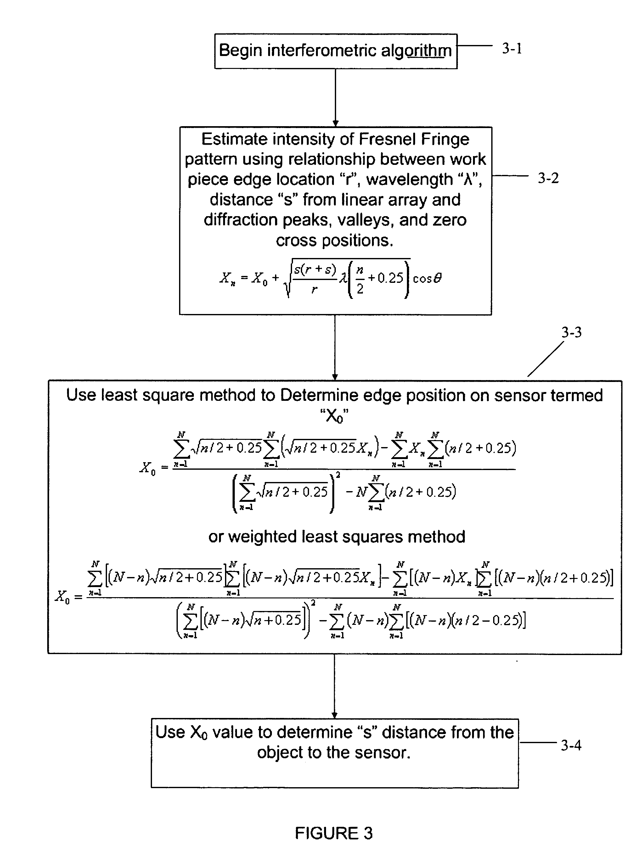
[0029] Prior art apparatus and methods do not improve or refine the sensed sensor array data by using the detailed information derivable from Fresnel near field diffraction and interference theory. As stated in the Background above, broadband light sources with gray scale solutions are commonly used instead. Significantly, the preferred embodiment uses Fresnel near-field...


PUM


Abstract

A non-contact gauge and method of use is provided for optical measurement of an object or objects. The apparatus and methods may comprise a laser providing a projected laser beam; a work-piece holder for holding the object to be measured; a light sensitive sensor located to sense the beam as the beam is diffracted by at least one edge of the object and as the beam forms a near field Fresnel diffraction fringe pattern upon elements of the sensor. The laser and the sensor are located to enable near-field Fresnel diffraction. A fringe pattern signal analyzer may be included for computing mathematical algorithms to determine the position (X0) of at least one edge of the object based upon the diffraction pattern sensed by the sensor wherein the fringe pattern signal analyzer is structured to refine sensed fringe pattern edge position data to be more accurate based upon a theoretical diffraction compensation factor.

Description

CROSS-REFERENCE TO RELATED APPLICATIONS [0001] This application claims priority under 35 U.S.C. § 119(e) to provisional U.S. patent application No. 60 / 507,340 filed Sep. 30, 2003, the entire disclosure of which is hereby incorporated by reference.BACKGROUND [0002] The commercial field of non-contact optical dimension gauging has remained fairly constant over the last two decades. The current state of the art uses two primary methods: scanning and projection. [0003] The scanning technique passes a collimated beam over a part, refocusing the beam down to a single photo diode, measuring the time the beam was in the shadow of the part and correlating the shadow time to the part size. [0004] The projection technique measures the size of the shadow cast by a collimated beam whose width is greater than the measured part. Current products using the projection technique make use of CCD's (Charge Coupled Devices), or other electronic capture detectors such as CMOS(Complimentary Metal Oxide Se...

Claims


Application Information

Patent Timeline
IPC IPC(8): G01B11/02
CPCG01B11/028G01B11/024
Inventor ZHAO, BINGBUDLESKI, WILLIAMMIDDELAER, WILLWENDT, KENNETH
Owner PRATT & WHITNEY MEASUREMENT SYST
Learn More