
Method and apparatus for increasing video streams in a video system

a video system and video stream technology, applied in the field of digital cable television, can solve the problems of high cost of current set-top units, high cost of all-digital environment, and the threat of digital tv to cable operators, and achieve the effect of simple switch and enhanced security

Inactive Publication Date: 2005-05-19
BARAN PAUL +3
View PDF3 Cites 205 Cited by
  • Summary
  • Abstract
  • Description
  • Claims
  • Application Information

AI Technical Summary

Benefits of technology

"The invention provides a new way to deliver new services to viewers without the need for expensive equipment like set-top boxes and head-end infrastructure. The invention uses existing plant without change, and co-exists with current cable system elements. The invention also includes a method and apparatus for controlling the start time of digital TV programs, allowing viewers to start watching sooner. The invention also includes a high-density RF generation and QAM system for a multi-channel digital TV system head end. The invention solves the problem of a single bottleneck of a CPU and RAM, resulting in a video server with many CPUs working in parallel to produce a much larger number of video streams. The invention also includes a distribution subsystem for distributing portions of the digitally-modulated signals for multiple TV distribution zones."

Problems solved by technology

The digital TV posed a competitive threat to the cable operators.
A pacing factor in the inevitable evolution of cable to an all-digital environment is the cost of the set-top unit.
Current set-top units are expensive, especially in the United States.
With a set-top unit required by each TV set, that displays digital signals, the cable industry faces an overly expensive investment unless an alternative is provided.
Digital processing and storage are continuing historic price declines.

Method used


Image

  • Method and apparatus for increasing video streams in a video system
  • Method and apparatus for increasing video streams in a video system
  • Method and apparatus for increasing video streams in a video system

Examples


Embodiment Construction

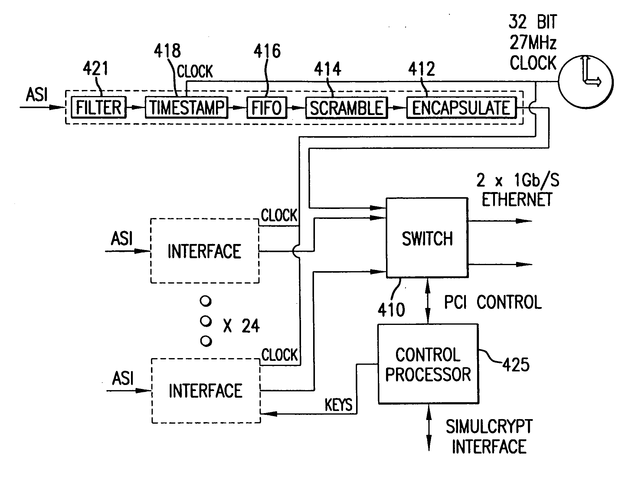
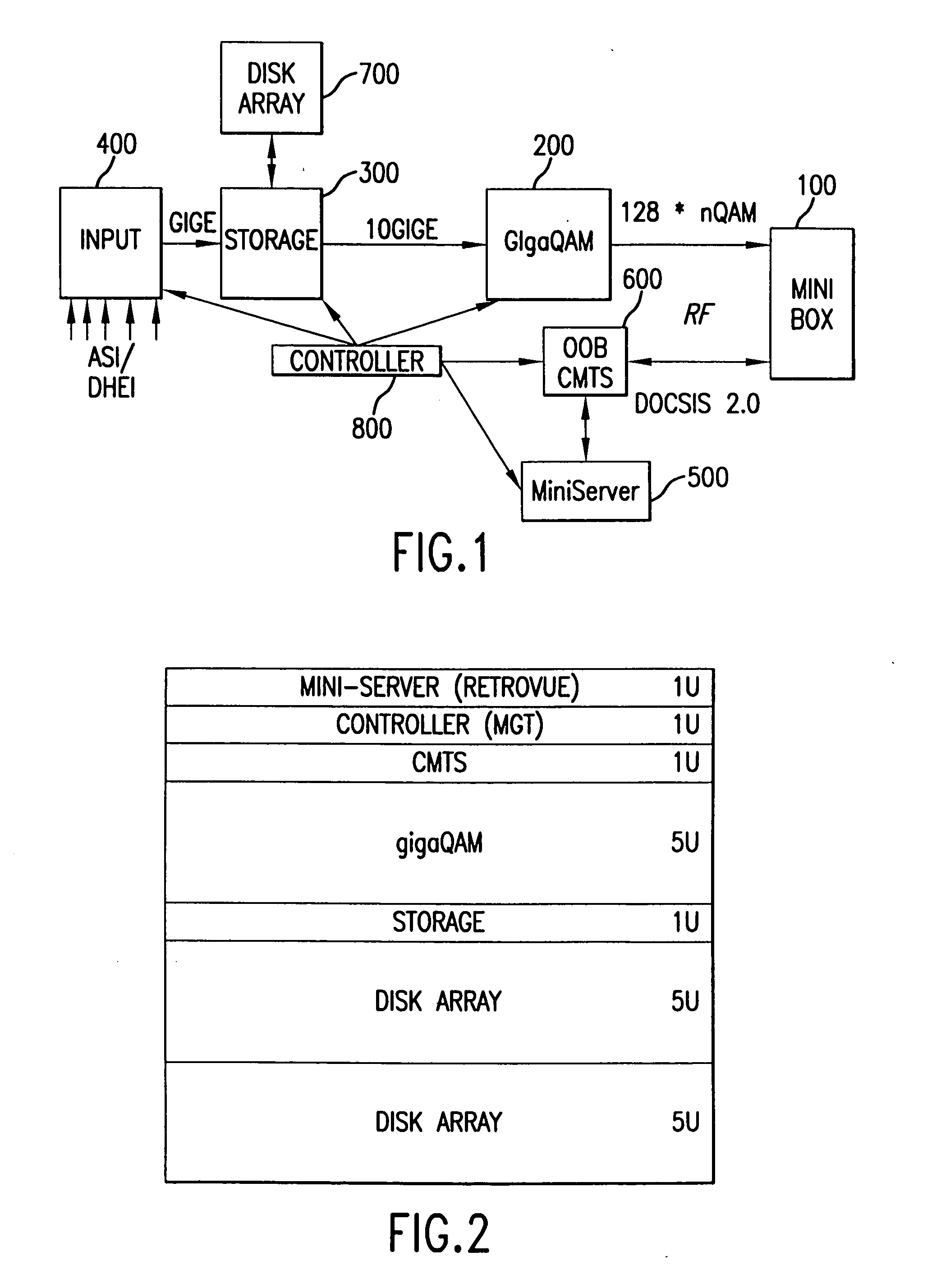
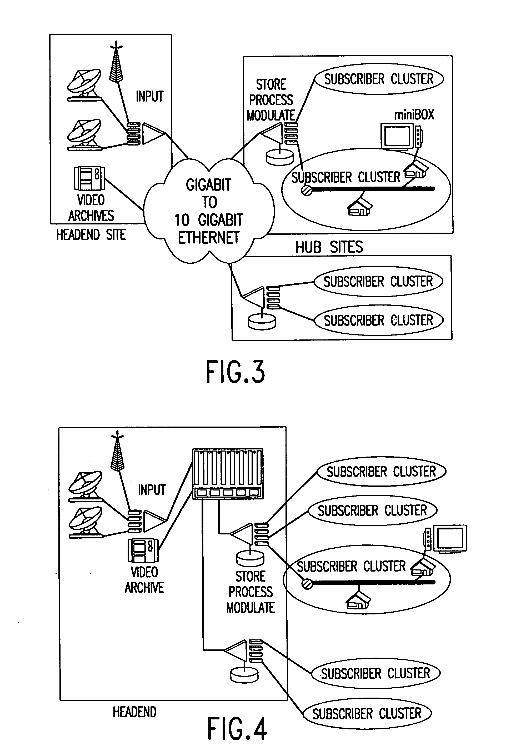
[0074] Reference now is made in detail to the present preferred embodiments of the invention, examples of which are illustrated in the accompanying drawings, wherein like reference numerals indicate like elements throughout the several views. Cable is the most successful last-mile technology for providing revenue-generating services to end-users, subscribers. The cable physical plant has evolved from a mostly one-way analog plant in the late 90's to today's two-way high-speed digital plant, with legacy analog support. The next major push within the cable industry is to enhance video service offerings and continue enhancing the two-way data environment. The ultimate target is the creation of the all-digital network, in which convergence of video, data, and voice and capacity are key attributes. The present invention is directed toward enabling the all-digital network with all-digital headend products, including high-speed data, Cable Modem Termination System (CMTS) and Cable Modem (C...


PUM


Abstract

A video system for providing a large number of video streams. The video system includes a video server and dividing means. Storage means, a switch and control means are located at the video server. The video server has a plurality of central-processing units (CPUs). The dividing means divides a plurality of input video-streams entering the video system, and sends the divided plurality of input-video streams, with each divided video stream identified with a separate Ethernet address, to the video server. The storage means stores an input video-stream of the plurality of input video-streams as a stored-video stream. The switch routes an input-video stream of the plurality of input-video streams to the storage means. The control means controls the storage means to replay the stored-video stream and to control portions of the stored-video stream at an appropriate time, and controls the plurality of CPUs at the video server to work in parallel.

Description

RELATED PATENT APPLICATIONS [0001] This patent stems from a divisional application of U.S. patent application Ser. No. 10 / 328,868, and filing date of Dec. 23, 2002, entitled METHOD AND APPARATUS FOR VIEWER CONTROL OF DIGITAL TV PROGRAM START TIME, with inventors PAUL BARAN, XU DUAN LIN, JOHN PICKENS and MICHAEL FIELD, and from a provisional patent application having Ser. No. 60 / 382,174, and filing date of May 21, 2002, entitled METHOD AND APPARATUS FOR VIEWER CONTROL OF DIGITAL TV PROGRAM START TIME, with inventors PAUL BARAN, XU DUAN LIN, JOHN PICKENS and MICHAEL FIELD, and a provisional patent application having Ser. No. 60 / 344,283, and filing date of Dec. 27, 2001, entitled MINI STE TOP BOX, with inventor PAUL BARAN. The benefit of the earlier filing dates of the prior applications is claimed for common subject matter.BACKGROUND OF THE INVENTION [0002] This invention relates to digital cable television, and more particularly to placing viewer in command of when the viewer chooses...

Claims


Application Information

Patent Timeline
Patent Type & Authority Applications(United States)
IPC IPC(8): H04L29/06H04N7/173H05K1/02H05K1/14H05K1/18
CPCH04L29/06027H04L65/4084H04L63/10H04N7/17318H04N21/2318H04N21/2326H04N21/23406H04N21/2347H04N21/2362H04N21/2365H04N21/26606H04N21/4347H04N21/47202H04N21/6405H04N21/6587H05K1/0275H05K1/144H05K1/185H05K2201/10151H04L63/068H04L65/612H04L65/1101
Inventor BARAN, PAULLIN, XU DUANPICKENS, JOHNFIELD, MICHAEL
Owner BARAN PAUL
Learn More