
Battery and method of manufacturing the battery

Inactive Publication Date: 2005-05-19
PANASONIC CORP
View PDF19 Cites 34 Cited by
  • Summary
  • Abstract
  • Description
  • Claims
  • Application Information

AI Technical Summary

Benefits of technology

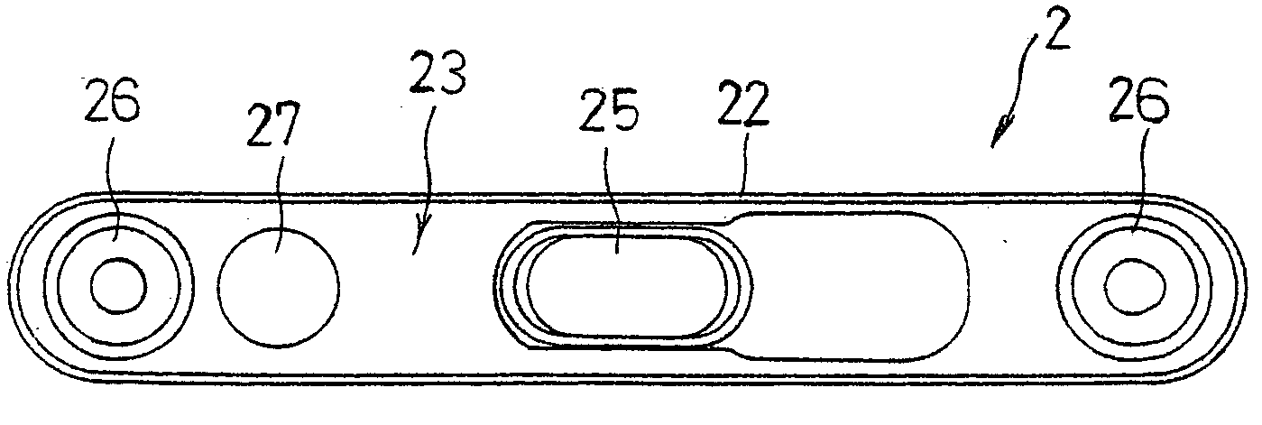
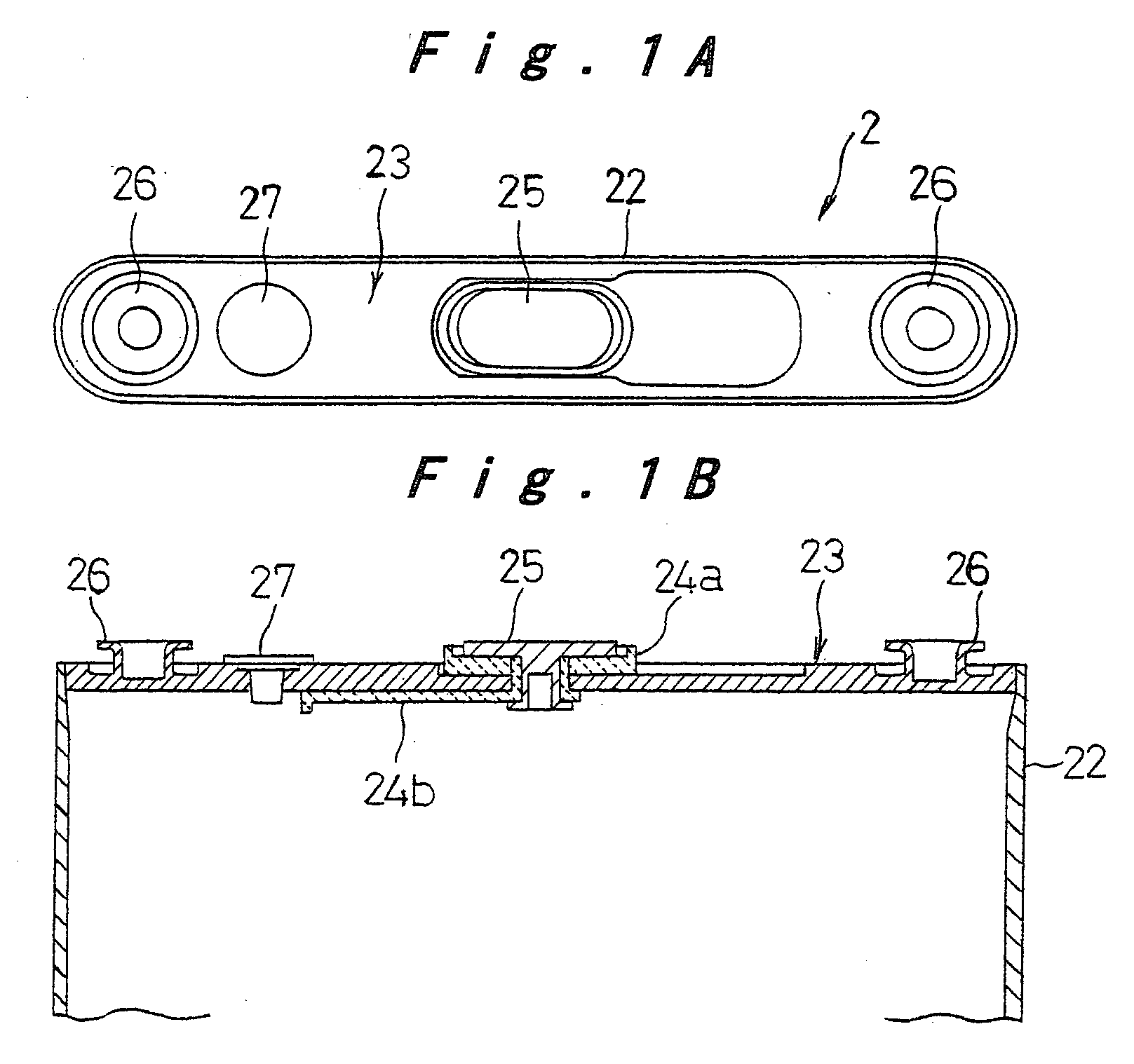
[0013] In the above structure, the protrusion and / or recess should preferably include an undercut portion that extends outward from the given surface, so that the undercut portion is embedded in the resin and provide an anchoring effect so as to ensure retention of resin.
[0018] The engaging member should preferably include an undercut portion that extends outward from the given surface, so that it provides an anchoring effect so as to ensure firm retention of resin on the battery.
[0020] If the given surface of the battery is made of aluminum, the above cylindrical engaging member should preferably be made of iron that is plated with copper and then tin, or aluminum, so that there will be less sparking during the welding and less variation in the welding strength, whereby a reliable weld will be formed.

Problems solved by technology

A temperature rise in the battery leads to a rapid increasing of gas pressure inside resulting from reactions between positive electrode active materials and electrolyte, or from evaporation or decomposition of electrolyte, which may cause fire or explosion of the battery.
However, battery packs using pack cases are not suited to portable electronic equipment that are re-modeled in short cycles, because the manufacturing cost of molding dies used in the resin molding of pack cases tends to be high, and the time required for designing new molding dies is relatively long.
Thinner battery packs with resin-molded pack case as an outer case also have limitations in making portable electronic equipment smaller and thinner because of the limitations on the moldable thickness in the resin molding process.
While the circuit substrate has various protrusions and recesses because of electronic components and lead plates connected thereto and can retain molded resin well, the rechargeable battery has fewer such protrusions and recesses even at the sealing part; because the rechargeable battery is formed of a metal material with a flat surface that can hardly form a good bond with resin, the filled resin can easily come off after curing, resulting in unstable bond between the circuit substrate and the rechargeable battery.
However, none of the above prior art examples shows a structure for retaining filled resin on the rechargeable battery; the resin may peel off when the rechargeable battery is subjected to an impact in a falling accident or the like and the circuit substrate may separate from the rechargeable battery, or, the battery may be disassembled for satisfying curiosity and put to wrong use because of the ease of disassembly.

Method used


Image

  • Battery and method of manufacturing the battery
  • Battery and method of manufacturing the battery
  • Battery and method of manufacturing the battery

Examples


Embodiment Construction

[0041] Preferred embodiments of the present invention will be hereinafter described with reference to the accompanying drawings for an understanding of the invention. It should be understood that the following embodiments of the invention are merely given as examples and should not limit the technical scope of the invention.

[0042] The present embodiment shows one example of a battery pack employing a flat prismatic lithium ion rechargeable battery that is united with a circuit substrate including a battery protective circuit by resin molding and applied to a mobile phone. Battery packs for mobile phones need to be small, light-weight, and thin, and in addition, they are desired to have a high energy density in accordance with high functionality, a high mechanical strength to withstand impacts caused by a falling accident which is inevitable with portable equipment, a structure that does not allow easy disassembling, and safety features for protecting the rechargeable battery from s...


PUM

PropertyMeasurementUnit
Pressureaaaaaaaaaa
Shapeaaaaaaaaaa

Abstract

A circuit substrate (3) being electrically connected to a rechargeable battery (2) is arranged upon a sealing plate (23) with a gap therebetween and united with the rechargeable battery (2) by filling resin in the gap. A primary mold (11) formed by the resin is firmly retained by undercut portions formed in engaging protrusions (26). The engaging protrusions (26) may be formed by welding separate engaging members (126, 126a, 126b, 126c, 66, 68).

Description

TECHNICAL FIELD [0001] The present invention relates to a battery formed with engaging parts to retain resin on a given surface of the battery to fixedly unite the battery with a circuit substrate formed with a battery protection circuit and external terminals by the resin to form a battery pack, and a manufacturing method thereof. BACKGROUND ART [0002] With the remarkable development of small, thin, and high-functionality portable electronic equipment such as mobile phones and PDAs, there is a growing demand for smaller, thinner, and high-capacity batteries as their power source. Lithium ion rechargeable batteries can be designed small and high-capacity, and in particular, flat prismatic types are suitable in making the equipment thinner; they have therefore been increasingly used as the repeatedly usable rechargeable battery for portable electronic equipment. [0003] Because lithium ion rechargeable batteries have high energy density and contain a flammable organic solvent as elect...

Claims


Application Information

Patent Timeline
IPC IPC(8): H01M2/04H01M2/10H01M10/04H01M2/02
CPCH01M2/1038Y10T29/49108H01M10/425Y02E60/10H01M50/216Y02P70/50H01M50/20H01M50/10
Inventor KOZU, KATSUMIISHIMARU, TAKESHIKATAOKA, SATOSHITORIYAMA, KOICHIMIZUTA, MASAHIROKANEDA, MASAAKIMASUMOTO, KENJIN
Owner PANASONIC CORP
Learn More