Eureka AIR delivers breakthrough ideas for toughest innovation challenges, trusted by R&D personnel around the world.

Capsule endoscope

Inactive Publication Date: 2009-03-12
OLYMPUS MEDICAL SYST CORP
View PDF16 Cites 39 Cited by
  • Summary
  • Abstract
  • Description
  • Claims
  • Application Information

AI Technical Summary

Benefits of technology

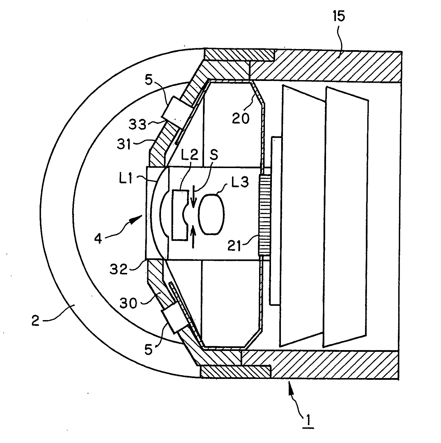
[0014]That is, to incline the angle of the light emitter devices located, they are attached to a flexible substrate; without any holder structure, however, the location of the light emitter devices would get erratic. Unless the angle of inclination is kept with high precision, there would be variations in the distributed light, and flares as well. By use of the integral-piece holder member, the light emitter devices attached to the flexible substrate remain fixed with more reliable alignment of the objective lens with the light emitter devices so that there can be less variations in the distributed light, and less unwanted light.
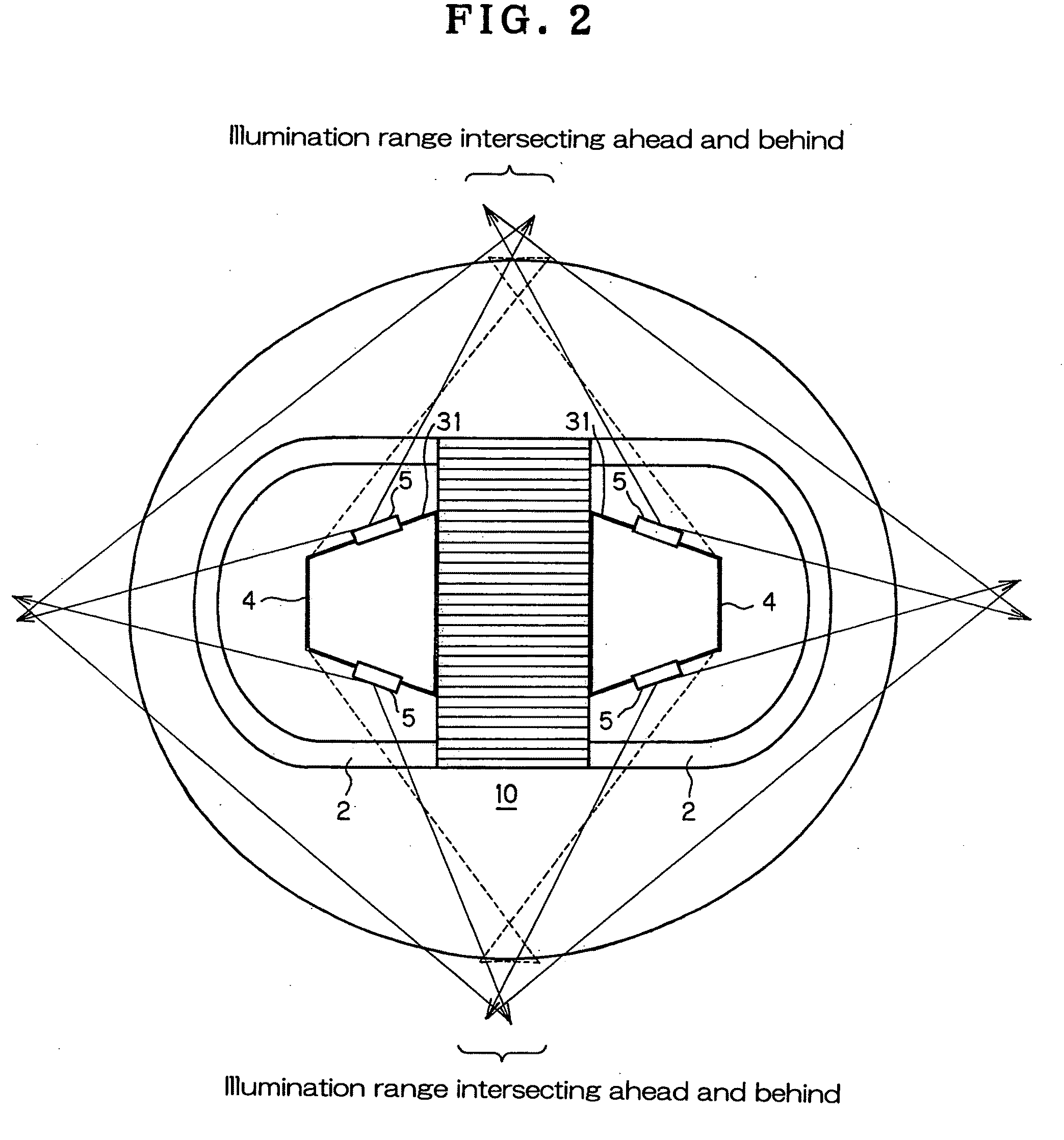
[0028]By locating two objective lenses each having an angle of field of 140° or greater in the ahead-and-behind direction to set up a binocular arrangement capable of viewing images nearly all around, it is possible to make substantial elimination of any blind spot. It is thus possible to get rid of blind spots even with a capsule endoscope having no function of changing the field direction freely and, hence, make improvements in screening capability.

Problems solved by technology

That is, to incline the angle of the light emitter devices located, they are attached to a flexible substrate; without any holder structure, however, the location of the light emitter devices would get erratic.

Method used


Image

  • Capsule endoscope
  • Capsule endoscope
  • Capsule endoscope

Examples


Embodiment Construction

[0040]Examples of the inventive capsule endoscope are now explained with reference to the accompanying drawings.

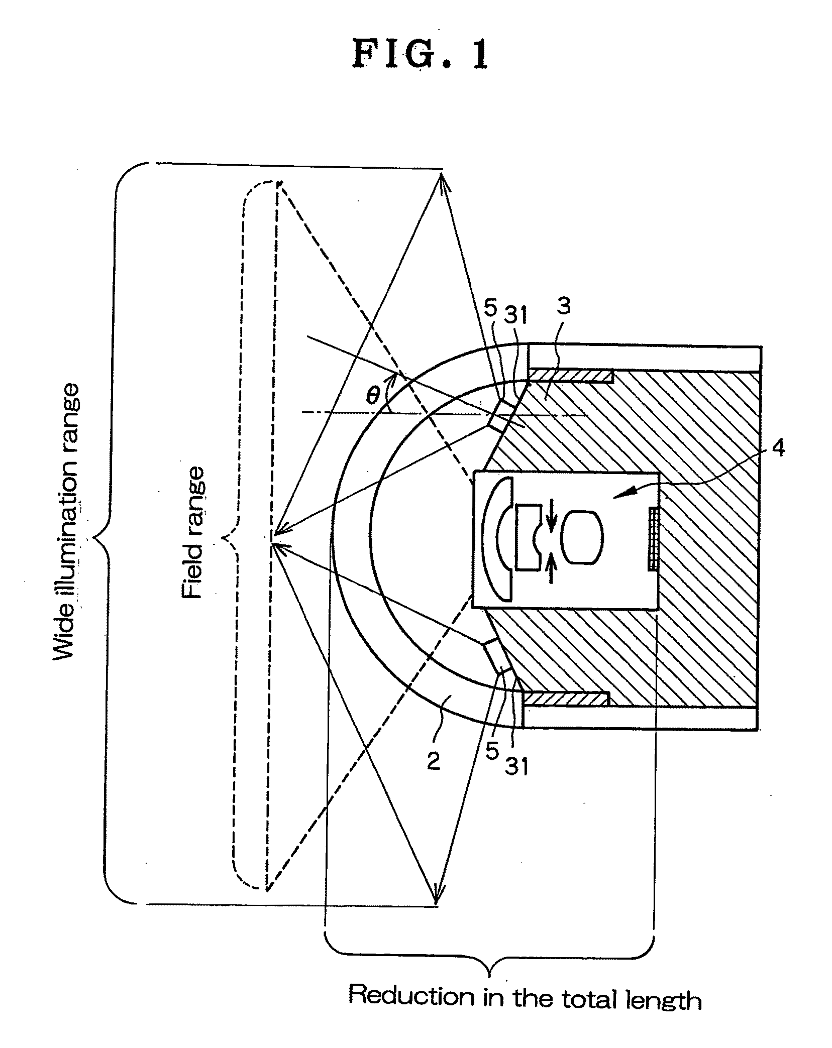
[0041]Referring to FIG. 8 that is illustrative of an end structure of a conventional capsule endoscope 1, a transparent, semispherical dome 2 is located over the end of the capsule endoscope 1; within the capsule endoscope 1 there is an objective lens 4 attached to the center of a frame member 3; and at a planar end of the frame member 3 around the objective lens 4 there are a plurality of light emitter devices 5 located symmetrically about the center axis, wherein each light emitter device comprises a light emitter diode (LED) or electroluminescent device (EL). In such arrangement, the field range (indicated by a broken line) of the objective lens 4 is included in the illumination range (indicated by a solid line) of the light emitter devices 5.

[0042]As end structures of such arrangement are located ahead and behind into a binocular type capsule endoscope 10, it causes a ...


PUM


Abstract

The invention relates to a capsule endoscope layout capable of achieving a small-format, wide-angle, wide light-distribution arrangement with limited variations. A capsule endoscope 1 comprises an objective lens 4, a transparent dome 2 to cover the object side of the objective lens, and light emitter devices located around the outer periphery of the objective lens. The endoscope 1 further comprises an integral-piece holder member 30 adapted to hold the objective lens 4 in place and hold the light emitter devices 5 at a position set back from an end of, and around, the objective lens 4 while the light emitter devices 5 are inclined outward at an angle with a center axis of said objective lens 4.

Description

BACKGROUND OF THE INVENTION[0001]The present invention relates generally to a capsule endoscope, and more particularly to an-optimum structure for wide-field observation by capsule endoscopes.[0002]Unlike conventional endoscopes, current capsule endoscopes have not a function of implementing in-vivo scans in any desired field direction; as compared with an endoscope having the same field range, a capsule endoscope would have a blind spot in a range incapable of changing the field of view, resulting in an increased probability of some oversight of lesions.[0003]For this reason, the capsule endoscope having no function of implementing scans over the field range is designed to have a wide-angle, ahead-and-behind binocular imaging system (Patent Publication 1) so that any blind spot can be eliminated to stave off the oversight of lesions; the binocular imaging system is said to be a function of urgent need.[0004]However, making the optical system a wide-angle arrangement leads to use of...

Claims


Application Information

Patent Timeline
IPC IPC(8): A61B1/06
CPCA61B1/0676A61B1/041A61B1/0605A61B1/0625
Inventor ORIHARA, TATSUYAFUKUHORI, HITOSHI
Owner OLYMPUS MEDICAL SYST CORP
Why Eureka
Eureka Blog
Learn More