
Frame rate conversion device, overtaking prediction method for use in the same, display control device and video receiving display device

a frame rate conversion and overtaking prediction technology, applied in the direction of instruments, television systems, color signal processing circuits, etc., can solve the problems of preventing methods that cannot be avoided, difficult to perform frame rate conversion under fixed conditions like single-picture displays, and difficulty in accurately predicting overtaking, etc., to achieve accurate overtaking prediction, improve accuracy, and prevent disturbances of display

Inactive Publication Date: 2005-05-19
CANON KK
View PDF15 Cites 35 Cited by
  • Summary
  • Abstract
  • Description
  • Claims
  • Application Information

AI Technical Summary

Benefits of technology

The invention provides a frame rate conversion device that can accurately predict when there will be an overtaking (when data is transferred between two memory locations) and prevent disturbances in display caused by overtaking. The device takes into account the offset difference between the input and output frames and uses a simple control circuit without increasing memory capacity. The device also includes an overtaking prediction unit that predicts the frame in which overtaking occurs, by using a combination of factors such as the difference in progress speed of the write and read addresses, the amount of memory address offset, and the difference in read and output frame rates. The device can adapt to changes in the input and output frame rates and can be used in multi-picture display configurations.

Problems solved by technology

The frame omission and the multiple display which occur due to this overtaking preventing method cannot be avoided when frame rate conversion is performed.
However, the case in which a video image contains images split within a frame due to overtaking causes a feeling of visual unnaturalness, and in this case and in general, an overtaking measure can be taken to reduce the feeling of visual unnaturalness.
Accordingly, since not only the timing formats of input and output differ from each other but also the frame rates of a plurality of inputs and a display output differ from each other, it is difficult to perform frame rate conversion under fixed conditions like single-picture display.
In other words, there is not a related art which takes into account the offset difference between an effective area and an input video effective area, so that accurate prediction of overtaking has heretofore been difficult.

Method used


Image

  • Frame rate conversion device, overtaking prediction method for use in the same, display control device and video receiving display device
  • Frame rate conversion device, overtaking prediction method for use in the same, display control device and video receiving display device
  • Frame rate conversion device, overtaking prediction method for use in the same, display control device and video receiving display device

Examples


first embodiment

[0062] (First Embodiment)

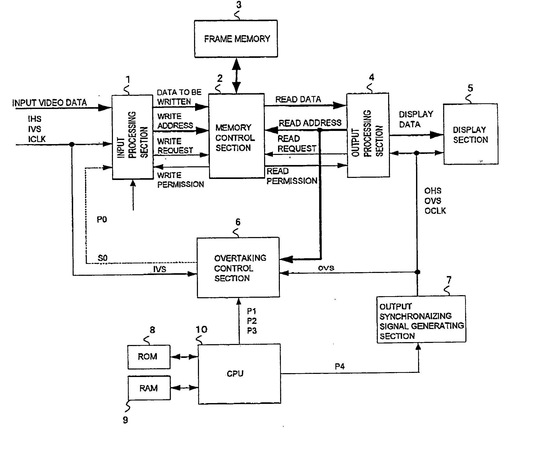
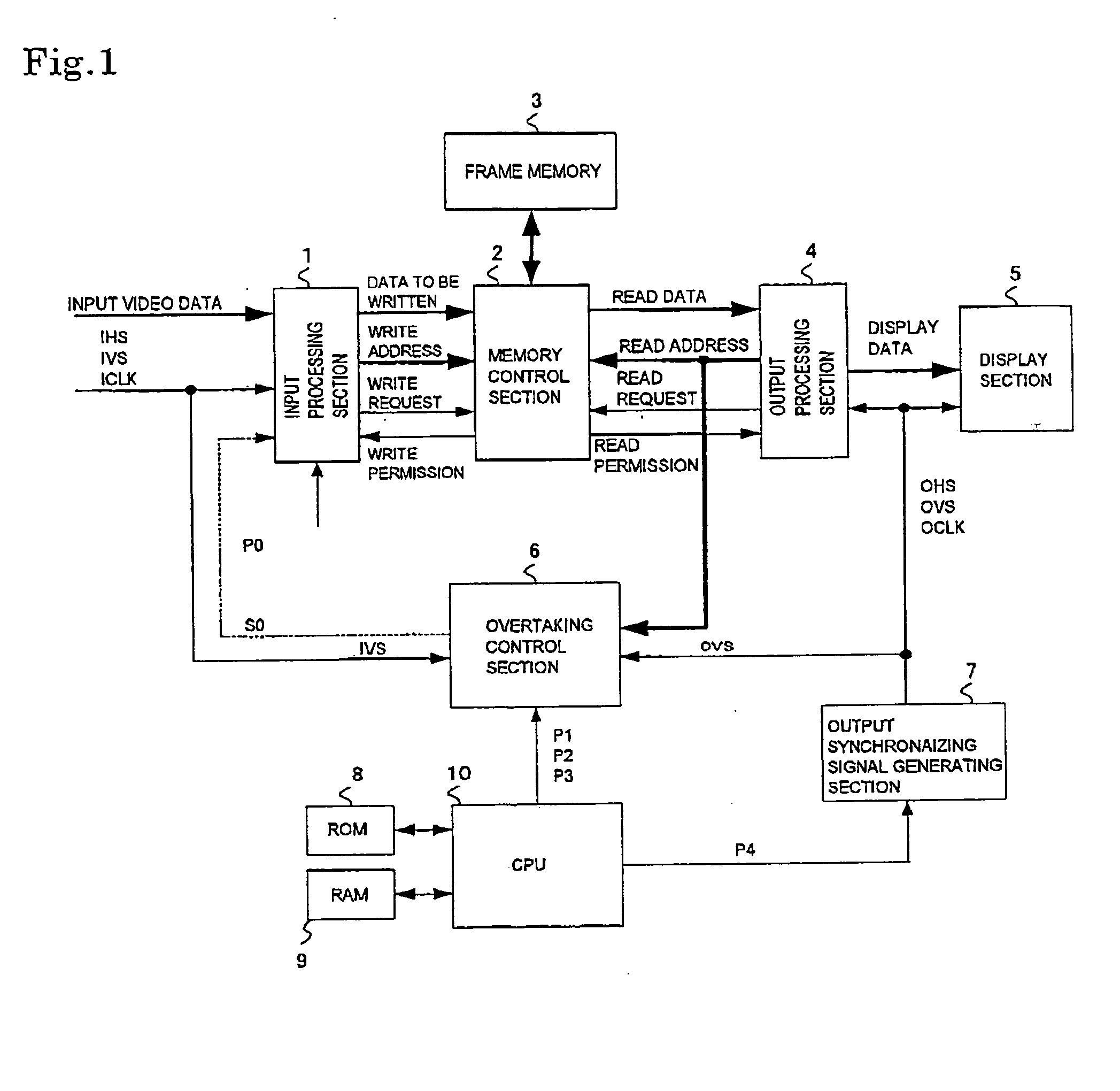
[0063]FIG. 1 shows a block diagram aiding in explaining an overtaking prediction control method according to the invention.

[0064]

[0065] The block diagram of FIG. 1 shows a frame synchronization circuit for single-picture display (one input, one output), a display control device provided with this frame synchronization circuit, and a display device provided with this display control device and a display section. Individual blocks will be described below.

[0066] An input processing section 1 receives input video data together with an input horizontal synchronizing signal (IHS), an input vertical synchronizing signal (IVS) and an input clock signal (ICLK), and performs image processing and scaling processing (resolution conversion) on the input video data and transfers the processed video data to a memory control section 2. The scaling processing is capable of enlargement or reduction to a desired magnification on the basis of a parameter indicative of a scali...

second embodiment

[0102] (Second Embodiment)

[0103] In the description of the first embodiment, reference has been made to the overtaking prediction method for the case of Fiv (input frame rate)>Fov (output frame rate). In the second embodiment, reference will be made to the opposite case.

[0104]

[0105]FIG. 5 is a timing chart aiding in explaining an overtaking prediction method for the case of Fiv (input frame rate)

[0106] In FIG. 5, the horizontal axis represents time and the vertical axis represents memory address, and the variations of an input (write) address are represented by solid lines and the variations of an output (read) address are represented by dashed lines.

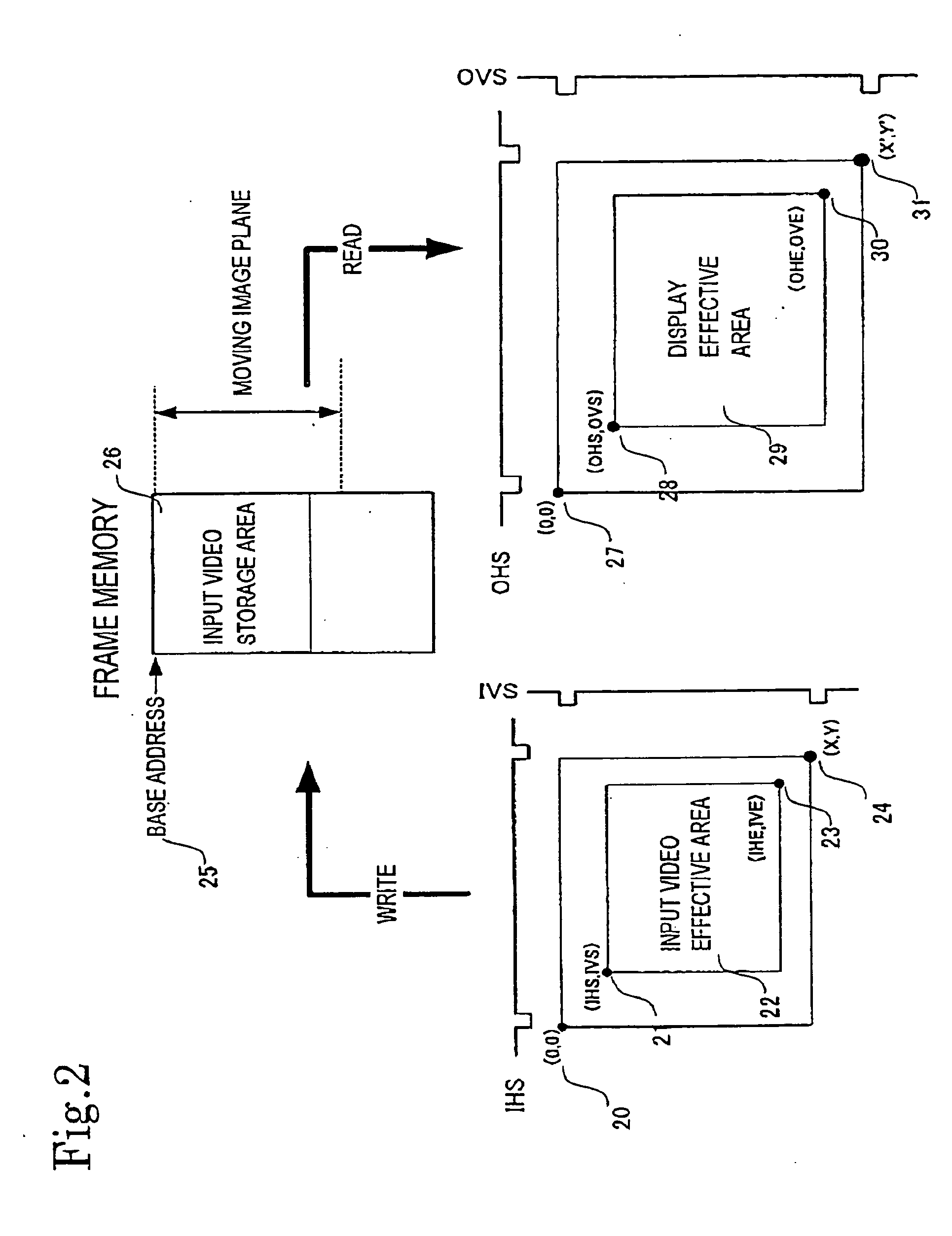
[0107] In FIG. 5, for ease of explanation, it is assumed that on the write side of FIG. 2, the point 20 (0, 0)=the point 21 (IHS, IVS) and the point 23 (IHE, IVE) the point 24 (X, Y), that on the read side of FIG. 2, the point 27 (0, 0)=the point 28 (OHS, OVS) and the point 30 (OHE, OVE)=the point 31 (X′, Y′)...

third embodiment

[0123] (Third Embodiment)

[0124] In the respective first and second embodiments, the overtaking prediction method for the case of Fiv (input frame rate)>Fov (output frame rate) and the overtaking prediction method for the case of Fiv (input frame rate)6 capable of coping with a system incapable of determining in advance which of the cases occurs will be described below with reference to FIG. 7.

[0125] A correction circuit 11 receives a read address from the output processing section 4 and performs the correction expressed by Expression (5) on the basis of input offset information (P2) and output offset information (P3) from the CPU 10, thereby generating the corrected read address M′. The corrected read address M′ is transferred to a comparator 12 and a comparator 13 at the same time. The comparator 12 receives from the CPU 10 the threshold constant K (P1) for Fiv (input frame rate)>Fov (output frame rate), and performs the threshold decision comparison expressed by Expression (4).

[...


PUM


Abstract

An overtaking prediction method of, when input and output of data to and from a common memory are being performed with an input frame frequency and an output frame frequency made different from each other, predicting a frame in which overtaking occurs between the input and the output of the data to and from the memory. The overtaking prediction method includes a step of predicting the frame in which the overtaking occurs between the input and the output of the data, on the basis of a first parameter corresponding to a difference amount between a progress speed of a write address and a progress speed of a read address and a second parameter corresponding to a difference between a write address and a read address at an overtaking prediction point and to an offset address difference amount between an input offset address and an output offset address.

Description

BACKGROUND OF THE INVENTION [0001] 1. Field of the Invention [0002] The present invention relates to a frame rate conversion device using overtaking prediction, and an overtaking prediction method for use in the same. A video receiving display apparatus such as TV system is provided with the frame rate conversion device. [0003] 2. Description of the Related Art [0004] In the broadcasting industry, the transition from analog terrestrial broadcasting to BS / CS / terrestrial digital broadcasting, so-called digitization of broadcasting, is currently proceeding. At the same time, the role of television is also greatly changing from “TV set placed in living room” toward “information window of home”. This trend of digitization increases the number of programs to be sent to each home (an increase in the number of channels), and the amount of information of video is also increasing from SD (Standard Definition) toward HD (High Definition). [0005] The roles of display devices are also changing u...

Claims


Application Information

Patent Timeline
Patent Type & Authority Applications(United States)
IPC IPC(8): H04N7/24G06F3/14G09G1/16G09G5/00G09G5/12G09G5/39H04N7/01
CPCG06F3/14G09G5/001G09G5/006G09G5/12G09G5/39H04N7/0105G09G2320/0261G09G2340/0435G09G2340/125G09G2360/02G09G2360/18G09G5/397H04N5/45H04N7/01H04N21/44
Inventor YUI, HIDEAKIMATSUZAKI, EIICHI
Owner CANON KK
Learn More