
Halar membranes

a technology of halar membranes and membranes, applied in the field of halar membranes, can solve the problems of high pressure needed, uneven wetness, and damage to membranes, and achieve the effect of less or reducing the effect of human health and the environment, and low toxicity

Inactive Publication Date: 2005-05-12
EVOQUA WATER TECH LLC
View PDF99 Cites 72 Cited by
  • Summary
  • Abstract
  • Description
  • Claims
  • Application Information

AI Technical Summary

Benefits of technology

[0052] Preferably, the porous polymeric membranes of the present invention have one or more of the following properties: high permeability (for example, greater than 1000 LMH / hr@100 KPa), good macroscopic integrity, uniform wall thickness and high mechanical strength (for example, the breakforce extension is greater than 1.3N).

Problems solved by technology

Water can be forced through a hydrophobic membrane by use of sufficient pressure, but the pressure needed is very high (150-300 psi), and a membrane may be damaged at such pressures and generally does not become wetted evenly.
Some hydrophilic materials are not suitable for microfiltration and ultrafiltration membranes that require mechanical strength and thermal stability since water molecules can play the role of plasticizers.
Even at low concentrations, a high throughput of chlorinated water can expose membranes to large amounts of chlorine over the working life of a membrane can lead to yellowing or brittleness which are signs of degradation of the membrane.
Syneresis of the solvent from the polymer results in shrinkage and cracking, thus forming interconnections or pores between the cells.
In many cases it is also difficult to state which is the solvent and which is the solute.
The previous methods were not amenable to producing hollow fibres and moreover, utilised solvents which are highly toxic with high environmental impact, such as 1,3,5-trichlorobenzene, dibutyl phthalate and dioctyl phthalate.
While these desiderata have been established for some time, it was hitherto unknown how to fulfil the long felt need to make hollow fibre membranes from such a desirable compound.
Further, a disadvantage in relation to the existing prepararatory methods for Halar flat sheet membranes is that they require the use of highly toxic solvents or solvents that are of dubious safety at the very least.
Such difficult solvents are required due to the chemical stability of Halar and its resistance to most common solvents below 150° C.

Method used


Image

  • Halar membranes
  • Halar membranes
  • Halar membranes

Examples


Embodiment Construction

[0098] The TIPS process is described in more detail in PCT AU94 / 00198 (WO 94 / 17204) AU 653528, the contents of which are incorporated herein by reference. The current method used to prepare the membranes of the present invention is described herein in simplified form.

[0099] In one preferred form of the invention, poly (ethylene chlorotrifluoroethylene) is formed as a hollow fibre. The poly (ethylene chlorotrifluoroethylene) is dissolved in a suitable solvent and then passed through an annular co-extrusion head.

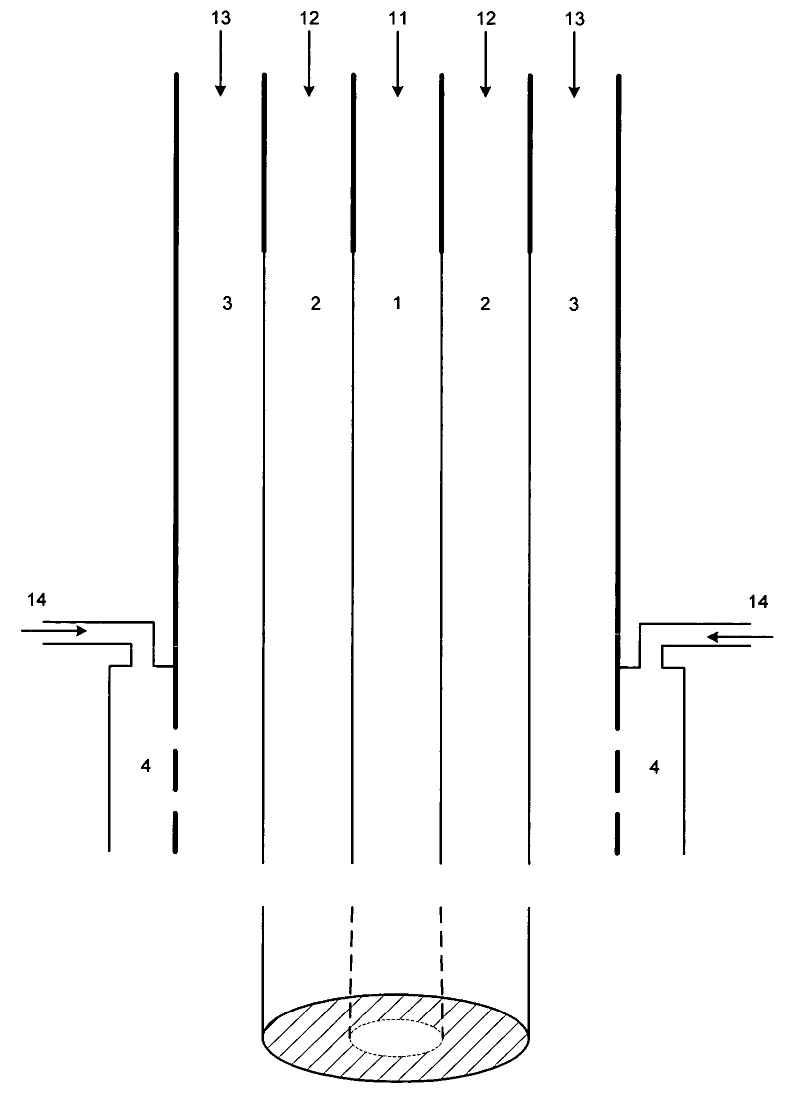
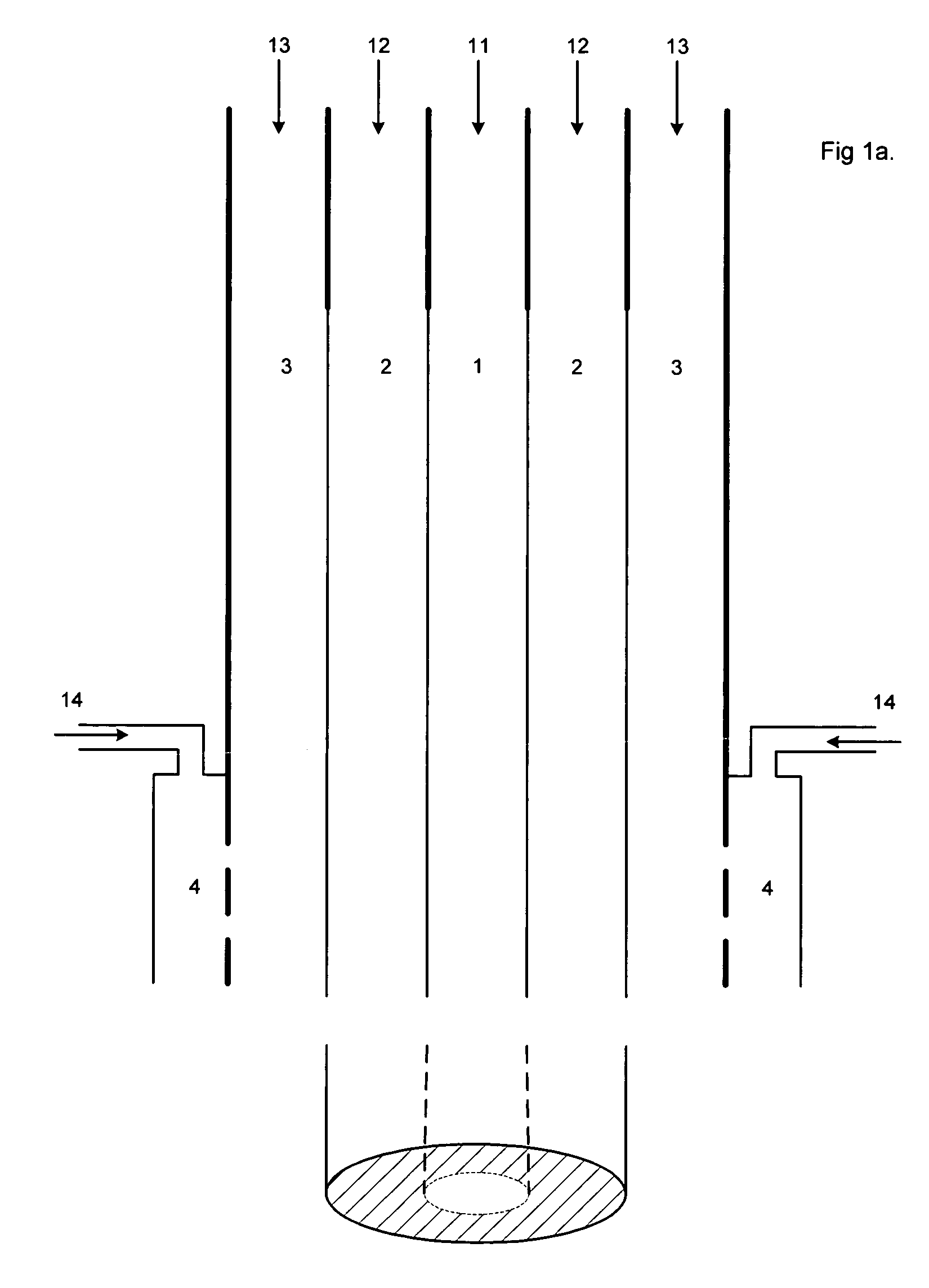
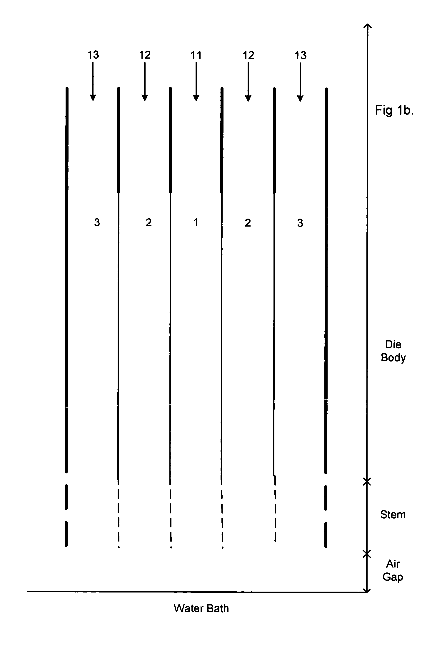
[0100] There are two possible ways to conduct the methods of the present invention in relation to hollow fibres. One is via a coextrusion head having three concentric passageways, as shown in cross section FIG. 1b, the other is via a quadruple co-extrusion head having four concentric passageways is shown in cross section in FIG. 1a. The principle is broadly the same in both cases, except for the way the quench fluid is contacted with the fibre.

[0101] In both cases, the axia...


PUM

PropertyMeasurementUnit
Temperatureaaaaaaaaaa
Pore sizeaaaaaaaaaa

Abstract

Porous polymeric membranes including Halar (poly (ethylene chlorotrifluoroethylene)) and related compounds and the methods of production thereof which avoid the use of toxic solvents. Preferred solvents, coating agents and pore forming agents are citric acid ethyl ester or glycerol triacetate. The membranes may be in the form of a hollow fibre or flat sheet, and may include other agents to modify the properties of the membrane, such as the hydrophilic / hydrophobic balance. Leachable agents may also be incorporated into the membranes.

Description

RELATED APPLICATIONS [0001] This application is a continuation, under 35 U.S.C. § 120, of International Patent Application No. PCT / AU03 / 00179, filed on Feb. 12, 2003 under the Patent Cooperation Treaty (PCT), which was published by the International Bureau in English on Aug. 21, 2003, which designates the United States, and which claims the benefit of Australian Provisional Patent Application No. PS 0466, filed Feb. 12, 2002.FIELD OF THE INVENTION [0002] The invention relates to Halar (ethylene chlorotrifluoroethylene copolymer, or poly (ethylene chlorotrifluoroethylene)) and related membranes for use in ultrafiltration and microfiltration and in particular to membranes in the form of hollow fibres, and to methods of preparing said membranes. BACKGROUND OF THE INVENTION [0003] The following discussion is not to be construed as an admission with regard to the common general knowledge in Australia. [0004] Synthetic polymeric membranes are well known in the field of ultrafiltration and...

Claims


Application Information

Patent Timeline
IPC IPC(8): B01D67/00B01D69/08B01D71/32B29C67/20D01D5/24
CPCB01D67/0018B01D67/0027B01D67/0088B01D69/08B01D71/32B29C67/202D01D5/24B01D2323/08B01D2323/18B01D2323/22B01D2325/022B01D2325/20B01D2325/36B01D2325/38B01D67/003Y10T428/249958B01D2323/081B01D67/0031B01D2325/0231
Inventor MULLETTE, DANIELMULLER, HEINZ-JOACHIM
Owner EVOQUA WATER TECH LLC
Learn More