Method and magnetic resonance imaging apparatus for compensating contrast inhomogeneities in magnetic resonance images

a magnetic resonance image and contrast inhomogeneity technology, applied in the field of magnetic resonance imaging apparatus for compensating contrast inhomogeneities in magnetic resonance images, can solve the problems of unsatisfactory dependency, unsuitable universal functional configuration, and unsuitable for every body and position, and achieve good compensation for contrast inhomogeneities

Inactive Publication Date: 2005-04-21
SIEMENS HEALTHCARE GMBH
View PDF17 Cites 25 Cited by
  • Summary
  • Abstract
  • Description
  • Claims
  • Application Information

AI Technical Summary

Benefits of technology

[0008] An object of the present invention is to provide an alternative to the described state of the art which in a relatively simple and universal way enables good compensation for contrast inhomogeneities in magnetic resonance imaging arising from the spatial distribution of the radio frequency field.
[0017] In one particularly simple variant of the process, for each image pixel of the contrast-homogenized image, the intensities of the corresponding pixel in the different individual images are added up. Alternatively, a simple average value of the of the intensities of the corresponding pixels in the different individual images can be obtained. These methods are particularly applicable if radio frequency pulse sequences, for example spin-echo variants, are used for measurement which have the property that the signal intensity drops off quickly for actual flip angles which differ significantly from the target flip angle. This automatically leads to the maximum intensities of the individual images always being located where the actual flip angles lie close to the target flip angle. Thus a simple summation or average can ensure that in the contrast-homogenized image exactly those measurements dominate in the various locations in which the achieved flip angle is in the same range as the desired target flip angle.
[0028] Most preferably, the refocusing pulses are not emitted slice-selectively, that is, only the excitation pulse itself is transmitted slice-selectively. In this way, it can be avoided that the flip angle distribution measured in the process and caused by the penetration behavior of the radio frequency field may be overlaid by a flip angle distribution along the slice norm, caused by the slice selection itself.
[0030] Since it is necessary in the inventive process to acquire more than one image in each region to be examined, there is naturally an increased measurement cost, that is, the measurement time is increased. The contrast of an image, however, is largely determined by the central rows of the Fourier space (k-space). Thus it is generally sufficient to record one individual image with a complete sampling of the entire Fourier space. For all the rest of the images, then, only the central k-space rows must be re-recorded, that is, measured with modified flip angles. The central k-space rows of the different measurements can then be filled in by adding the previously measured outside rows of the completely recorded image. In this way, complete images with identical resolution can be generated.
[0031] This depends on the fact that the smaller location frequencies are seen in the middle range of k-space, that is, locations which encode information about large, relatively homogeneous areas in the location space. Data entries exhibiting strong intensity shifts, are placed by the Fourier transform in the outer rows of k-space, particularly the corners. By repeated measurement of the rows of Fourier space lying in the central region, primarily those regions are thus measured repeatedly which are large and relatively homogeneous. Assuming a primarily slowly spatially varying distribution of the transmitted B1 field, the acquisition of this data suffices for the generation of a contrast-homogenized image. The measurement time required is thus significantly reduced. Depending on the number of individual images used, the measurement time sometimes increases only by 10% in this manner in comparison to the recording of a non-homogenized individual image. It should be noted that even if only the rows in the central region of k-space are recorded, still the entire slice in location space is taken into account.
[0032] The inventive process thus offers the possibility of achieving a contrast-homogenization with relatively low increased cost, universally for any type of imaging (that is, for gradient echo processes, spin-echo processes, etc.), and for any subject. No additional hardware is required. Only corresponding software modules must be installed in the device control system and / or the image processing system, so that the process is also very well suited for upgrading existing magnetic resonance measurement systems.

Problems solved by technology

Insofar as a spatial distribution of the amplitude of the radio frequency field and thus the flip angle exists, the result is an undesired dependency of the image contrast on the spatial position, since the intensity distribution caused by the field distribution overlays the intensity distribution of the measured parameters (such as, for example, the tissue material in each position), which contains the image information.
This sort of undesired amplitude distributions of the radio frequency field occur due to the penetration behavior of the radio frequency field in dielectric and conductive media, particularly in zones of high magnetic field strengths of over 3 Teslas, or due to the use of local transmission coils or transmission arrays.
However, until now there has been no universally functional configuration applicable for every body and every position.
A practical implementation of this concept is thus not currently foreseeable.
This process, however, has the disadvantage that the necessary radio frequency pulses turn out to be very long and radio frequency-intensive.

Method used


Image

  • Method and magnetic resonance imaging apparatus for compensating contrast inhomogeneities in magnetic resonance images
  • Method and magnetic resonance imaging apparatus for compensating contrast inhomogeneities in magnetic resonance images
  • Method and magnetic resonance imaging apparatus for compensating contrast inhomogeneities in magnetic resonance images

Examples


Embodiment Construction

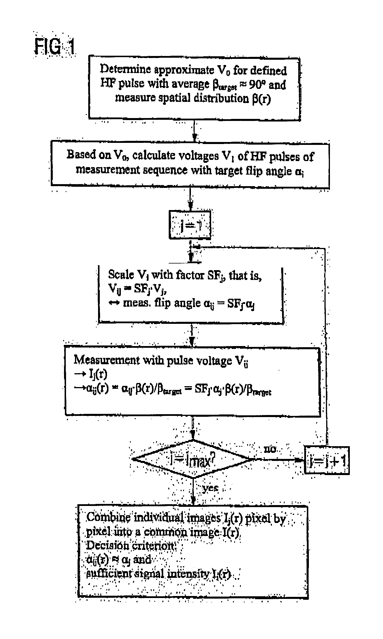
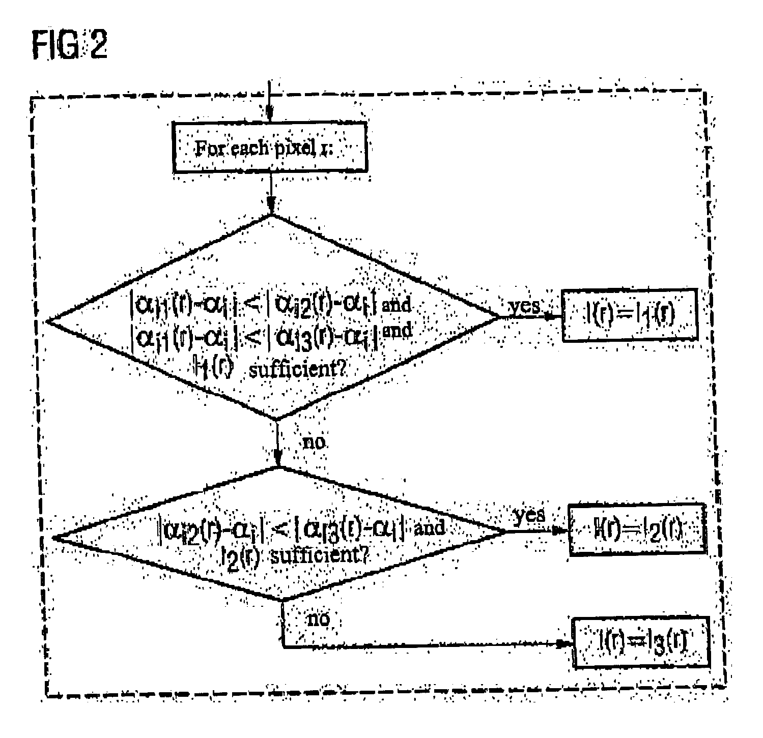
[0040] The inventive process is basically exemplified in FIGS. 1 through 5 using flowcharts, where FIG. 1 generally describes the measurement process and FIGS. 2 through 5 respectively show different possibilities for the combination of tho individual images into a common contrast-homogenized image.

[0041] As shown in FIG. 1, before the measurement, an estimated value V0 is determined in a first process step for the radio frequency pulse voltage which will generate an average spin angle βtarget of about 90° with a defined radio frequency pulse in the volume examined. Then a process to be described later will be used to measure the spatial distribution β(r).

[0042] Next, in a second process step, based on the derived voltage V0, a voltage V1 is calculated for the radio frequency pulse of a measurement sequence for the planned examination with N target flip angles αi (i=1 to N). In such a measurement sequence, depending on the task at hand, there are different radio frequency pulses w...


PUM


Abstract

In a method and magnetic resonance apparatus for compensation of contrast inhomogeneities in magnetic resonance images caused by spatial distributions of the radio frequency field associated with the radio frequency pulses that are emitted in order to acquire magnetic resonance (MR) data, multiple individual MR images of a particular region of a subject are recorded with different radio frequency pulse sequences leading to different flip angles. A common contrast-homogenized image for the affected region then is generated based on the different individual images, so that within the contrast-homogenized image, intensity variations due to a distribution of the flip angle are smaller than in the individual images, at least in some areas.

Description

BACKGROUND OF THE INVENTION [0001] 1. Field of the Invention [0002] The present invention concerns a process for the compensation of contrast inhomogeneities in magnetic resonance images caused by spatial distributions of the radio frequency field associated with the radio frequency pulses that are emitted in order to excite nuclear spins in the subject. The invention also concerns a magnetic resonance measurement system with a contrast homogenization feature in order to compensate for such contrast inhomogeneities in acquired magnetic resonance images. [0003] 2. Description of the Prior Art [0004] Magnetic resonance imaging, also called magnetic resonance tomography, is a technique that is now widespread for acquiring images of the body interior of a living object to be examined. In order to acquire an image with this method, the body or the body part to be examined must first be exposed to a homogenous static basic magnetic field (usually characterized as a B0 field), which is gen...

Claims


Application Information

Patent Timeline
Patent Type & Authority Applications(United States)
IPC IPC(8): G01R33/565
CPCG01R33/5659
Inventor FEIWEIER, THORSTENHEBRANK, FRANZ
Owner SIEMENS HEALTHCARE GMBH
Why Eureka
Try Eureka