
Active probe for an atomic force microscope and method for use thereof

a technology of atomic force microscope and active probe, which is applied in the direction of mechanical roughness/irregularity measurement, process and machine control, instruments, etc., can solve the problem of general limit of the speed of a standard afm in cyclical mode, and achieve high-speed imaging and accurate z position measurements.

Inactive Publication Date: 2005-03-31
BRUKER NANO INC
View PDF4 Cites 52 Cited by
  • Summary
  • Abstract
  • Description
  • Claims
  • Application Information

AI Technical Summary

Benefits of technology

The present invention combines an AFM Z position actuator and a self-actuated Z position cantilever (both operable in cyclical mode and contact mode), with appropriately nested feedback control circuitry to achieve high-speed imaging and accurate Z position measurements. Most generally, the feedback signals applied to each of the actuators can be independently monitored to indicate the topography of the sample surface, depending upon the scan rate and sample topography.
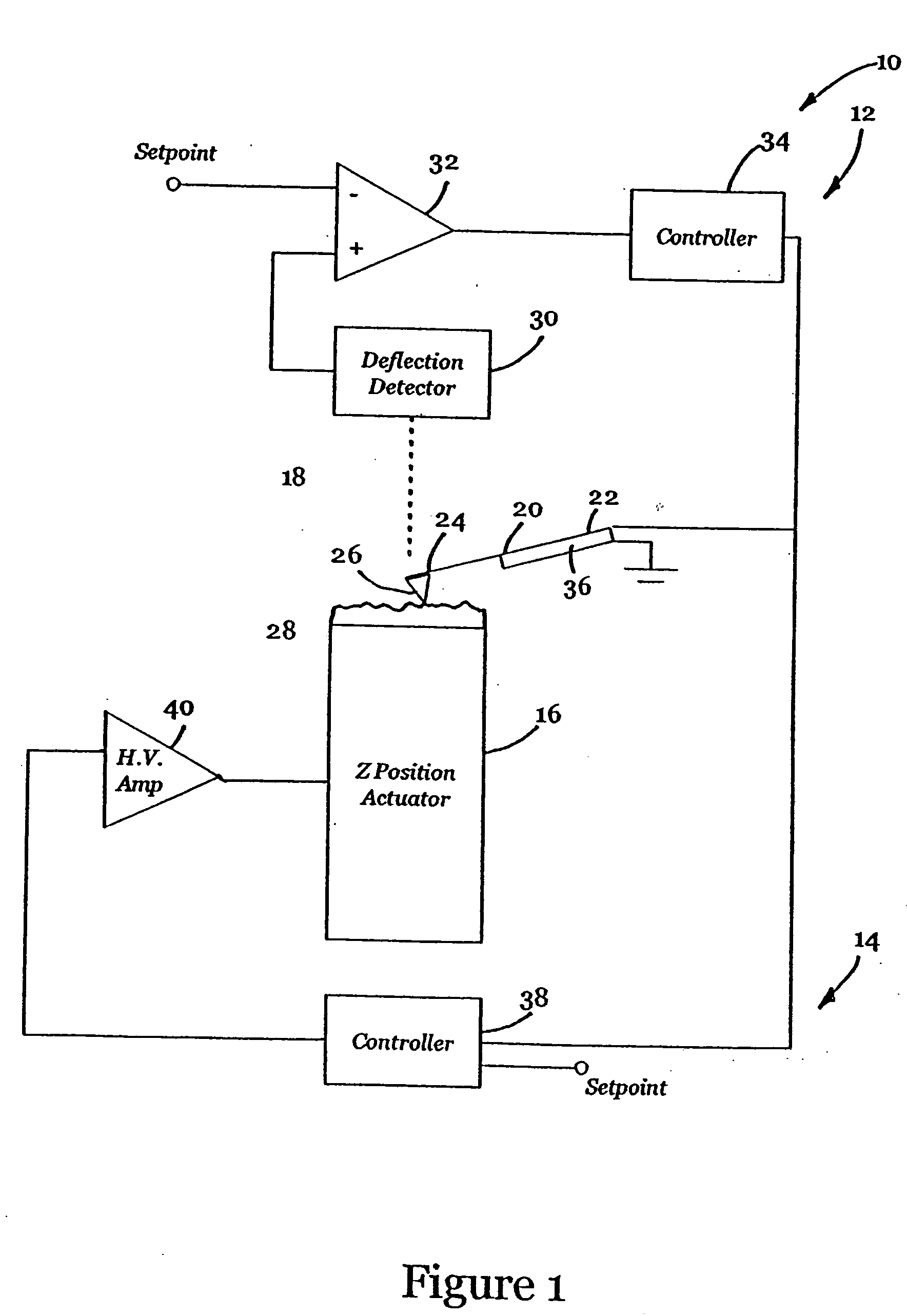
In one embodiment of the present invention, the lower frequency topography features of a sample, including the slope of the sample surface, are followed by a standard Z actuator while the high frequency components of the surface topography are followed by the self-actuated cantilever. Preferably, two feedback loops are employed. The first feedback loop controls the self-actuated cantilever to maintain a relatively constant force between the tip of the cantilever and the sample surface. The second feedback loop controls the standard Z actuator, at a lower speed than the first feedback loop and serves either (1) to keep the self-actuated cantilever within its operating Z range or (2) to maintain the linearity of the positioning sensitivity of the cantilever when following low frequency topography. This embodiment also allows for the standard Z actuator to be exclusively used for accurate height measurements when the scan rate is sufficiently lowered, typically less than 500 μm / sec.
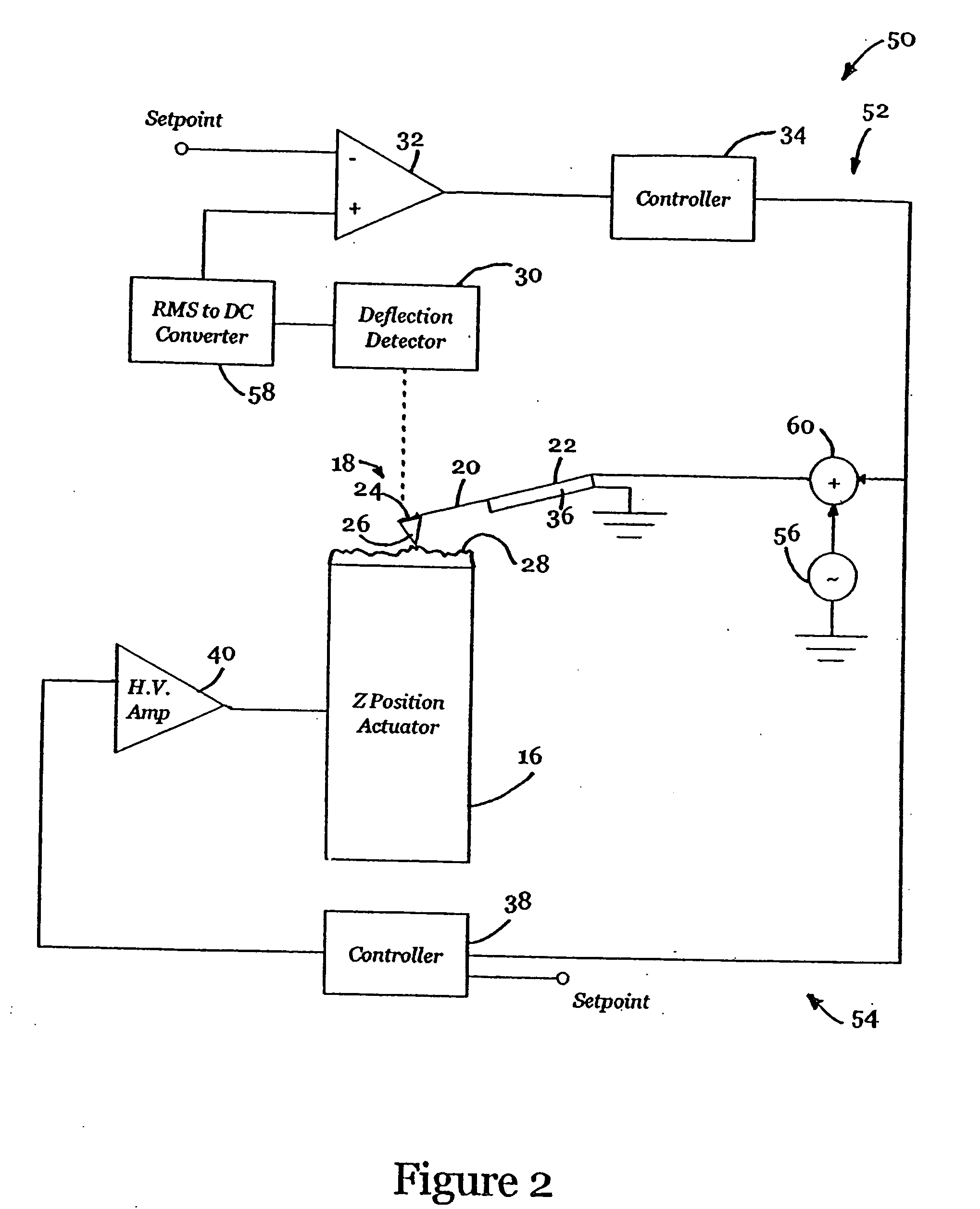
According to a preferred embodiment of the present invention, an AFM which operates in cyclical mode (i.e., TappingMode™) combines both the AFM Z actuator and the self-actuated cantilever with appropriate feedback control in a system that oscillates the self-actuated actuator without introducing mechanical resonances other than that of the cantilever. Most notably, the self-actuated cantilever is not oscillated by vibrating a piezo-crystal mechanically coupled to the cantilever, but rather is oscillated at its resonance by directly exciting the piezoelectric material disposed thereon. This eliminates mechanical resonances in the coupling path which would otherwise be present.
As suggested above, the speed of a standard AFM in cyclical mode is generally limited by the loop bandwidth of the force detection circuitry and the Z positioning apparatus. A further limiting factor associated with standard AFMs pertains to phase shift contributions from the various components of the loop that accumulate to limit the gain of an otherwise stable operating system. Importantly, however, the self-actuated cantilever of the present invention does not have significant phase shift contributions at standard operating frequencies, even though the detection bandwidth of the AFM in cyclical mode is still limited by the width of the resonance peak of the cantilever. Therefore, the self-actuated cantilever feedback loop is considerably faster than the AFM Z position actuator feedback loop, when both are limited by the same detection bandwidth. Notably, this embodiment also increases the speed of the AFM Z actuator feedback loop by providing a larger error signal than that which is generated by the cyclical mode amplitude deflection detector.
In addition, the combination of the standard AFM Z actuator and the self-actuated cantilever allows for greater flexibility in fast scanning cyclical mode. When the Z actuator feedback loop is disabled or operating with low gain, the topography appears as the control signal to the self-actuated cantilever. This control signal preferably also serves as the error signal for the AFM Z actuator feedback loop. When the gain of the second feedback loop is optimized, i.e., when the Z actuator is operating as fast as possible without yielding unreliable output, the topography then appears in the control signal for the AFM Z position actuator. As a result, by incorporating the self-actuated cantilever within the control loop, the speed of obtaining highly accurate measurements can be increased. Also, as in the previous embodiment, the standard Z actuator can be used to remove slope or non-linearities from the scan in the case in which the self-actuated cantilever follows the topography of the sample surface. Further, as an alternative to a standard Z actuator such as a piezo-stack actuator, a thermal actuator disposed on the self-actuated cantilever can be used.
In yet another preferred embodiment, the AFM of the present invention is adapted for operation while at least partially submersed in fluid for imaging surfaces of, for example, biological substances. By using the integrated high speed actuator of the present invention to excite the resonance of the cantilever, the system eliminates disruptive acoustic excitations produced by a typical biological AFM which uses a piezo stack actuator. The integrated actuator can also perform the functions of the conventional tip / sample actuator, thus enhancing the bandwidth of the mechanical system. As a result, the AFM of the present invention is capable of imaging biological substances with increased imaging speed and integrity. In particular, the invention yields a clearly identifiable cantilever response (in both ambient air and fluid), thus allowing lower oscillatory drive voltages which, in turn, minimizes the forces between the tip and the sample. In addition, gasses (e.g., corrosive gasses) can be introduced into the system without damaging the probe. This capability permits the observance of real-time chemical reactions between the gas and, typically, the biological sample.

Problems solved by technology

As suggested above, the speed of a standard AFM in cyclical mode is generally limited by the loop bandwidth of the force detection circuitry and the Z positioning apparatus.
A further limiting factor associated with standard AFMs pertains to phase shift contributions from the various components of the loop that accumulate to limit the gain of an otherwise stable operating system.

Method used


Image

  • Active probe for an atomic force microscope and method for use thereof
  • Active probe for an atomic force microscope and method for use thereof
  • Active probe for an atomic force microscope and method for use thereof

Examples


Embodiment Construction

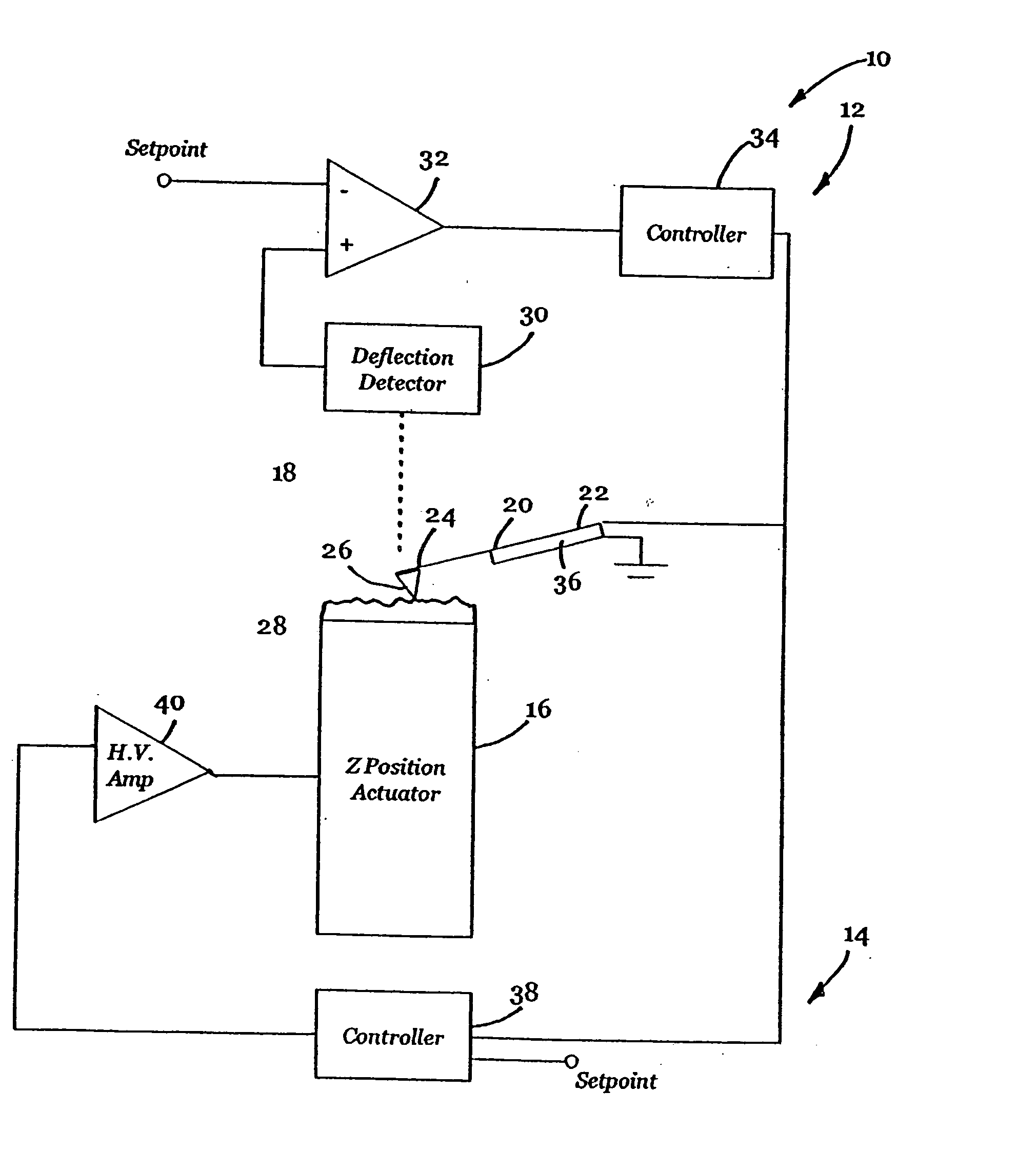
Referring to FIG. 1, an AFM 10 according to the present invention, which is configured for contact mode operation, is shown. AFM 10 includes two feedback loops 12 and 14 that control an AFM Z position actuator 16 and a probe assembly 18, respectively. Probe assembly 18 includes a self-actuated cantilever 20 having a tip 26 that interacts with a sample during scanning. When scanning in contact mode, tip 26 generally continually contacts the sample, only occasionally separating from the sample, if at all. For example, at the end of a line scan tip 26 may disengage the sample surface. While it scans the surface of the sample, cantilever 20 responds to the output of feedback loop-12 to ultimately map the topography of the surface of the sample, as described in further detail below.

Cantilever 20 includes a fixed end 22 preferably mounted to an AFM mount (not shown) and a free distal end 24, generally opposite fixed end 22, that receives tip 26. In operation, the interaction between ti...


PUM


Abstract

An AFM that combines an AFM Z position actuator and a self-actuated Z position cantilever (both operable in cyclical mode and contact mode), with appropriate nested feedback control circuitry to achieve high-speed imaging and accurate Z position measurements. A preferred embodiment of an AFM for analyzing a surface of a sample in either ambient air or fluid includes a self-actuated cantilever having a Z-positioning element integrated therewith and an oscillator that oscillates the self-actuated cantilever at a frequency generally equal to a resonant frequency of the self-actuated cantilever and at an oscillation amplitude generally equal to a setpoint value. The AFM includes a first feedback circuit nested within a second feedback circuit, wherein the first feedback circuit generates a cantilever control signal in response to vertical displacement of the self-actuated cantilever during a scanning operation, and the second feedback circuit is responsive to the cantilever control signal to generate a position control signal. A Z position actuator is also included within the second feedback circuit and is responsive to the position control signal to position the sample. In operation, preferably, the cantilever control signal alone is indicative of the topography of the sample surface. In a further embodiment, the first feedback circuit includes an active damping circuit for modifying the quality factor (“Q”) of the cantilever resonance to optimize the bandwidth of the cantilever response.

Description

BACKGROUND OF THE INVENTION 1. Field of the Invention The present invention relates to atomic force microscopes (AFMs) and, particularly, to an AFM and method of use thereof that combines an AFM Z position actuator and a self-actuated cantilever to provide high quality images at greatly increased data collection rates. 2. Description of the Related Art An Atomic Force Microscope (“AFM”), as described in U.S. Pat. No. RE34,489 to Hansma et al. (“Hansma”), is a type of scanning probe microscope (“SPM”). AFMs are high-resolution surface measuring instruments. Two general types of AFMs include contact mode (also known as repulsive mode) AFMs, and cyclical mode AFMs (periodically referred to herein as TappingMode™ AFMs). (Note that TappingMode™ is a registered trademark of Veeco Instruments, Inc. of Plainview, N.Y.) The contact mode AFM is described in detail in Hansma. Generally, the contact mode AFM is characterized by a probe having a bendable cantilever and a tip. The AFM operat...

Claims


Application Information

Patent Timeline
Patent Type & Authority Applications(United States)
IPC IPC(8): G01Q10/06G01B21/30G01Q20/02G01Q60/24G01Q60/34G05D3/00G05D3/12
CPCB82Y35/00G01Q10/045G01Q10/065G01Q60/34Y10S977/875Y10S977/869Y10S977/881Y10S977/849Y10S977/863Y10S977/851H01J37/26
Inventor ADDERTON, DENNIS M.MINNE, STEPHEN C.
Owner BRUKER NANO INC
Learn More